
Wiki article · Collection 04
DC/DC Converters
Engineering reference on DC/DC Converters for wireless power system design, integration, and deployment.
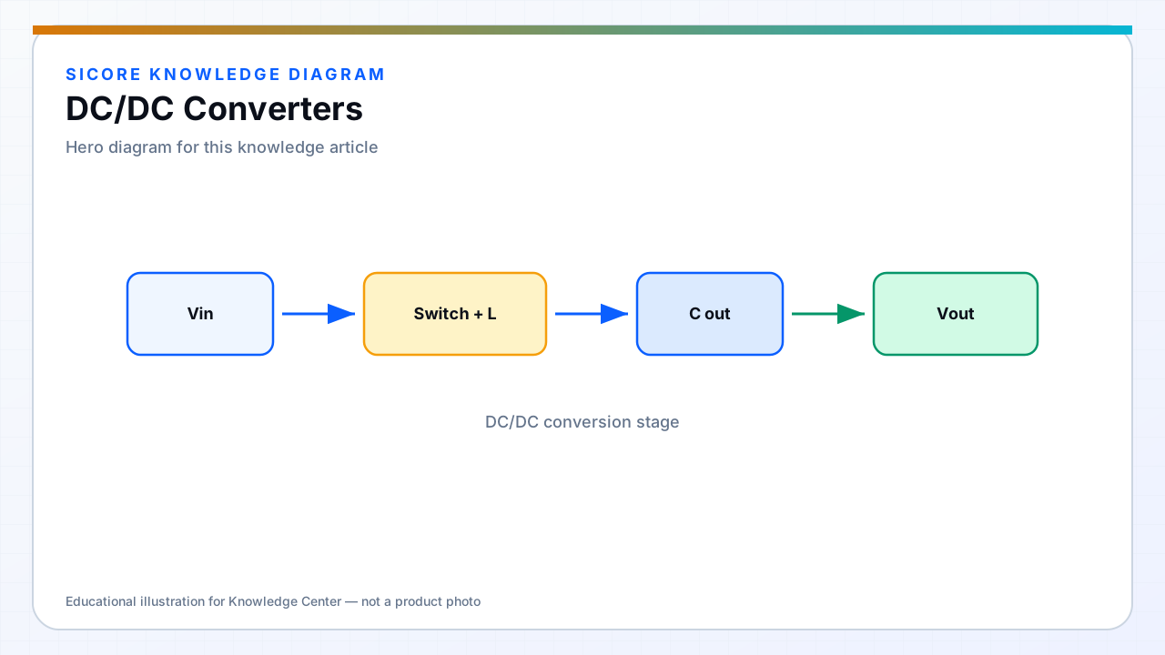
Wireless charging docks often include one or more DC/DC conversion stages between the facility input, the inverter DC bus, and the vehicle battery. On the vehicle, a DC/DC may sit after the WPT rectifier to match battery voltage, provide galvanic isolation, or interface traction and auxiliary buses.
Each conversion step adds loss but also decouples control domains — grid voltage swings do not directly modulate coil excitation, and battery chemistry sees a regulated charge profile.
01Where DC/DC appears
- Dock PFC output to regulated DC link feeding the WPT inverter.
- Vehicle receiver rectifier output to battery charge regulator.
- Auxiliary 24 V or 48 V supplies for AMR navigation electronics from the traction pack.
02Topology selection
Buck, boost, and buck-boost choices follow the voltage headroom between source and load. Isolated flyback or LLC-derived stages appear when safety standards require separation between user-accessible circuits and the coil primary. Efficiency targets for fleet economics favor synchronous topologies at the currents typical of industrial wireless power.
03System notes
- Coordinate switching frequencies to avoid beat tones on current sensors.
- Size input and output capacitors for both ripple and hot-plug on vehicle connect.
- Document efficiency maps alongside the WPT link — customers judge total dock-to-battery loss.