
Wiki article · Collection 04
Rectifiers
Engineering reference on Rectifiers for wireless power system design, integration, and deployment.
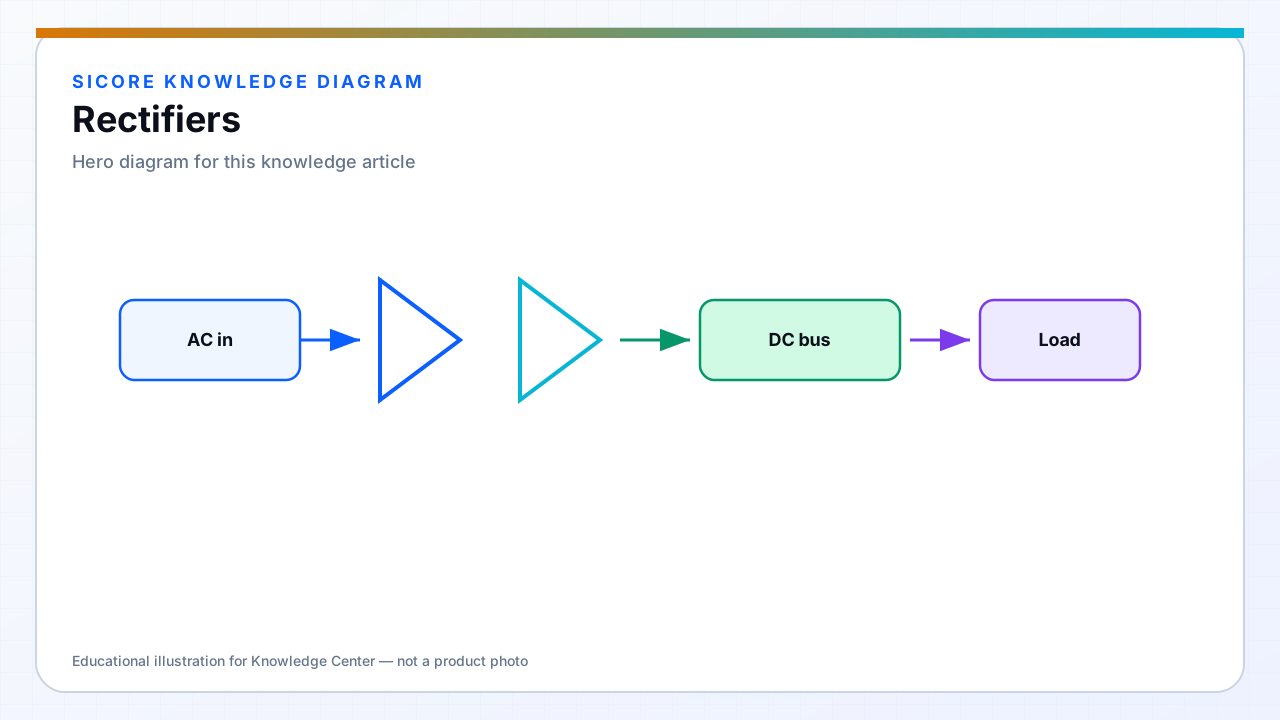
Rectifiers convert the AC or high-frequency AC from the receiver coil tank into DC for the battery or DC bus. In industrial wireless power for AGVs and AMRs, rectification happens on the vehicle side after resonant coupling — often at tens to hundreds of kilohertz rather than mains frequency.
The rectifier is not a passive afterthought. Its forward drop, reverse recovery, and layout parasitics add loss, heat, and EMI that propagate back through the tank and affect ZVS margins on the transmitter inverter.
01Common topologies in WPT
- Full-bridge diode rectifier for higher voltage receiver outputs.
- Center-tapped secondary with two-diode rectification when transformer or coil symmetry allows.
- Synchronous rectification when MOSFETs replace diodes for lower conduction loss at high current.

02Design priorities
Match rectifier voltage and current ratings to worst-case misalignment when coil voltage rises. Size output capacitors for ripple acceptable to the battery BMS and for hold-up during brief communication gaps. Place rectifier devices close to the coil secondary terminals to minimize loop area and ringing.
03Fleet considerations
- Document rectifier thermal limits — dock duty cycles can exceed lab average power.
- Plan for diode or SR FET replacement without recalibrating the entire receiver.
- Verify reverse voltage during load dump and unplug events, not only steady-state charging.