
Wiki article · Collection 04
Inverters
Engineering reference on Inverters for wireless power system design, integration, and deployment.
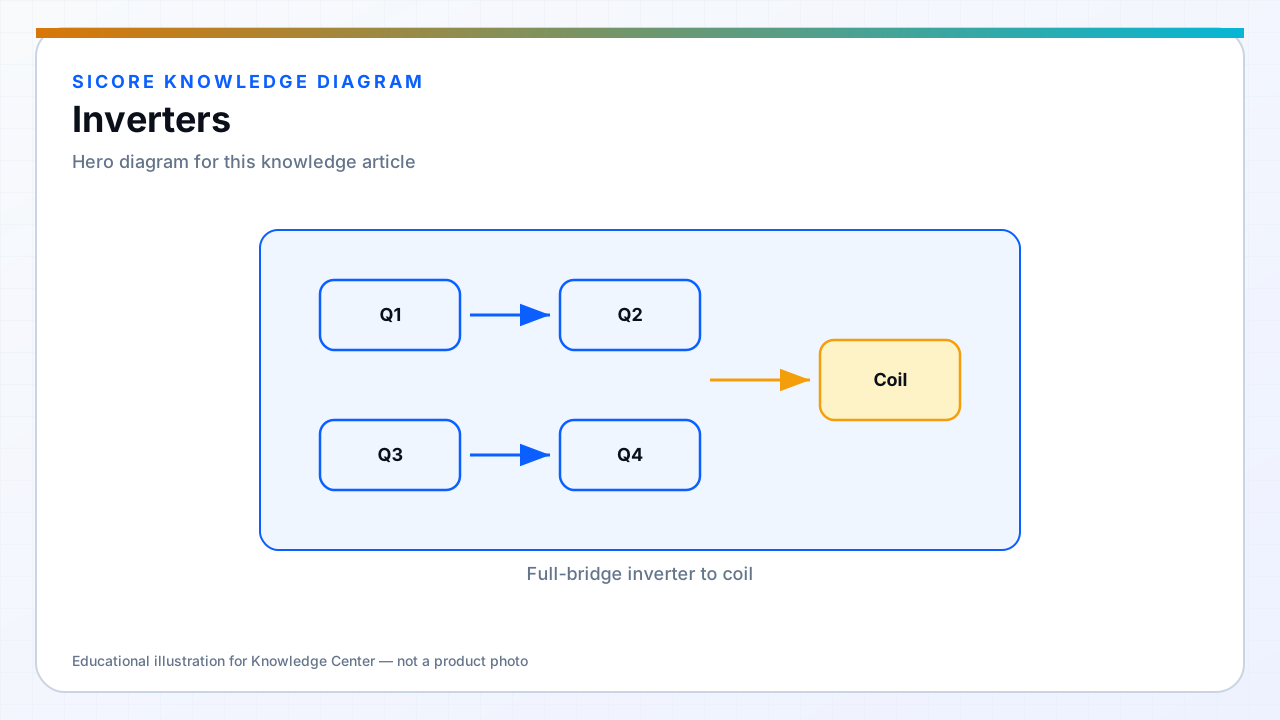
The dock-side inverter takes DC from the facility bus or PFC front end and synthesizes the AC waveform applied to the transmitter coil through a resonant tank. For AGV and AMR wireless charging, this is typically a half-bridge or full-bridge switching at the WPT operating frequency.
Inverter design sets switching loss, EMI spectrum, soft-switching capability, and how gracefully the dock responds to coupling changes as vehicles dock with varying alignment.
01Key inverter decisions
- Topology: half-bridge for moderate power density; full-bridge when voltage utilization or power scaling demands it.
- Modulation: fixed frequency with phase or frequency control depending on compensation network.
- Device technology: Si MOSFETs at lower frequency; SiC or GaN when switching loss dominates.
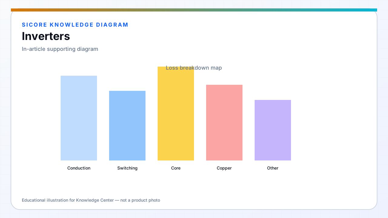
02Control coupling to the coil
The inverter does not operate in isolation. Tank impedance, coupling coefficient, and load resistance on the receiver jointly determine current and phase. Control loops must limit coil current and DC bus ripple while tracking charging requests from the vehicle over CAN or inductive communication.
03Dock integration
- Pre-charge and enable sequencing before full power — avoid slamming an unloaded tank.
- Fault ride-through for brief grid dips without tripping an entire charging row.
- Thermal derating coordinated with coil and magnetics, not inverter alone.