
Wiki article · Collection 04
MOSFET Selection
Engineering reference on MOSFET Selection for wireless power system design, integration, and deployment.
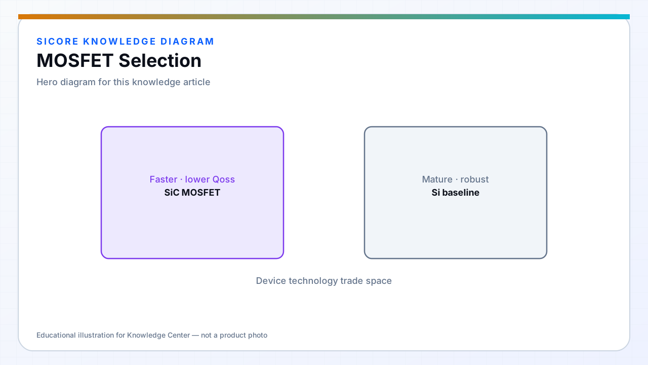
MOSFET selection balances conduction loss (I²RDS(on)), switching loss (Qg, Qoss, trr of body diode), and voltage rating for ringing and misalignment overshoot. In a charging dock inverter, the same part may see soft-switched operation at nominal load and hard switching during fault or startup.
Industrial wireless power favors parts with known avalanche behavior, consistent parametrics across batches, and availability for multi-year fleet spares.
01Selection criteria
- VDSS with margin above worst-case spike including layout overshoot.
- RDS(on) at operating junction temperature, not 25 °C datasheet.
- Gate charge versus driver capability — weak drive erases fast FET advantage.
- Body diode reverse recovery if it conducts during dead time or hard commutation.
02Si vs wide bandgap
Silicon superjunction MOSFETs remain cost-effective at moderate frequency. SiC and GaN extend frequency and efficiency when magnetics and layout can support faster edges. The winning device is the one that minimizes total loss at your frequency, current, and cooling budget — not the newest technology label.
03Validation
- Double-pulse testing on the actual PCB, not an evaluation board.
- Temperature cycling under dock enclosure limits.
- Spares and second-source policy before fleet lock-in.