
Wiki article · Collection 04
Switching Loss
Engineering reference on Switching Loss for wireless power system design, integration, and deployment.
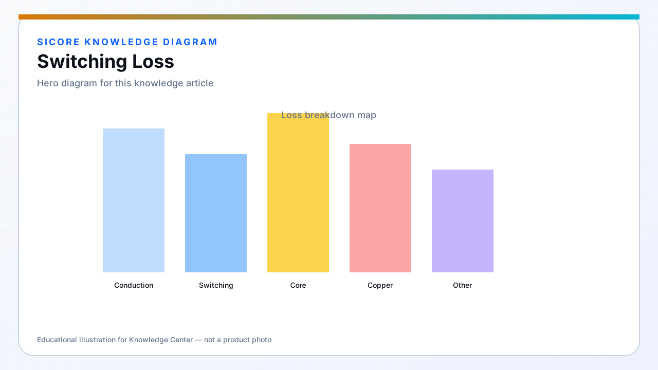
Switching loss occurs when the device conducts current while supporting voltage during turn-on and turn-off. In resonant wireless chargers, the goal is often zero-voltage switching (ZVS) so transitions happen near zero VDS. When ZVS is lost — light load, detuning, or fast transients — switching loss rises sharply.
Switching loss scales with frequency. Raising WPT frequency for smaller magnetics directly pressures the inverter unless commutation remains soft.
01Contributors
- Overlap of V and I during hard switching intervals.
- Output capacitance COSS dissipation during ZVS transitions.
- Gate drive speed — too slow increases overlap; too fast increases EMI and ringing.
- Reverse recovery of freewheeling or body diode paths.
02Mitigation strategies
Tune tank and control to maintain ZVS across coupling and load range. Select devices with favorable Qoss and Qg for your driver. Minimize loop inductance so voltage overshoot does not force conservative slow switching. Measure loss per switch with calorimetry or electrical loss breakdown, not datasheet alone.
03Fleet impact
- Dock efficiency maps must include switching loss at partial load where AGVs often sit.
- Thermal design sized for worst-case hard-switching fault modes.
- Log ZVS margin indicators for predictive maintenance on aging docks.