
Wiki article · Collection 01
Inductive Power Transfer (IPT)
Engineering reference on Inductive Power Transfer (IPT) for wireless power system design, integration, and deployment.
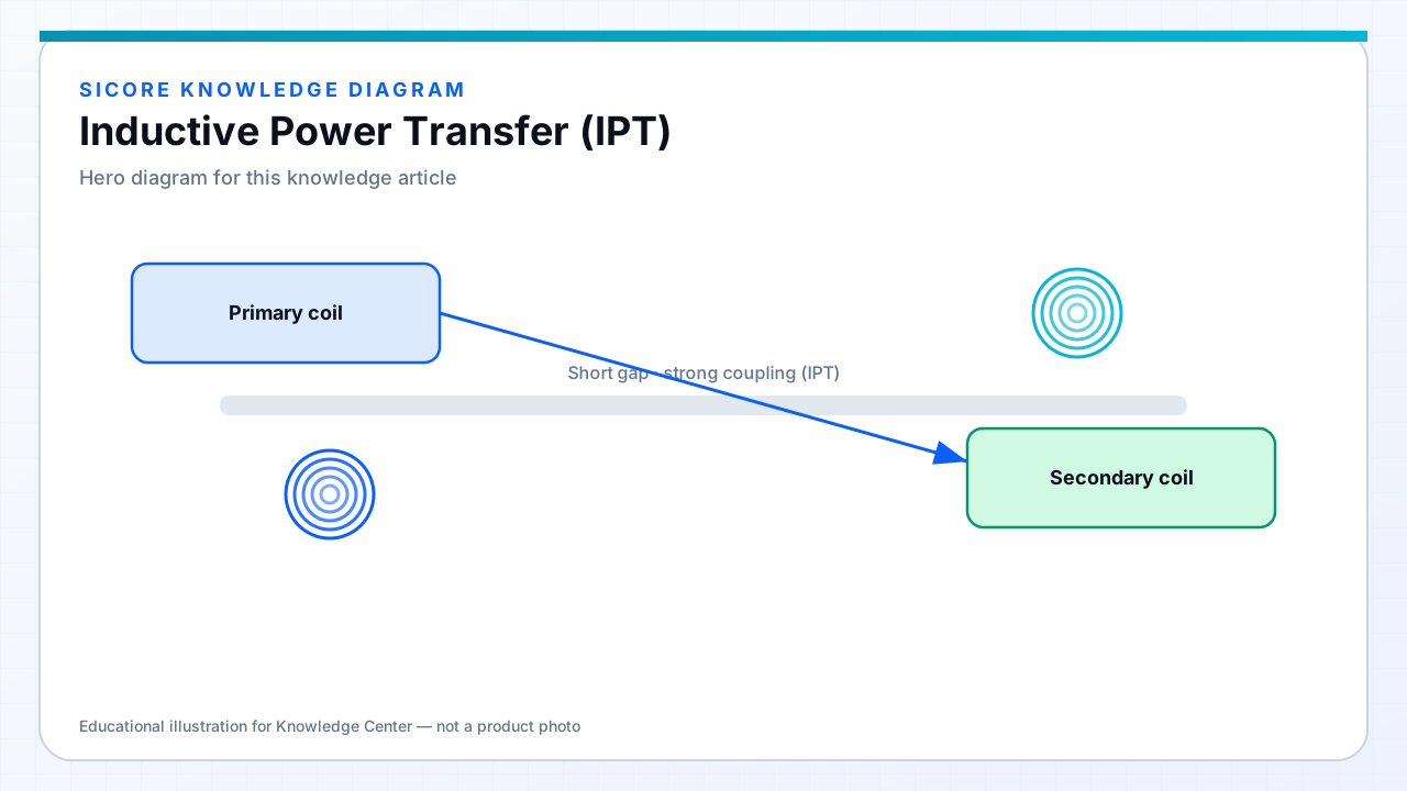
Inductive power transfer (IPT) uses a magnetic field between a transmitter coil and a receiver coil, similar to a transformer whose “core” includes a deliberate air gap. When the coils are close and well aligned, coupling is relatively strong and efficiency can be high.
01How IPT behaves
- Best performance at small air gaps (often millimeters to a few centimeters, design-dependent).
- Sensitive to lateral and angular misalignment compared with loosely coupled resonant systems.
- Common in pads, sealed docks, and connectors replaced by short-gap wireless interfaces.
- Frequencies are typically in the kHz to low-hundreds-of-kHz range for power stages, depending on magnetics and standards.

02Engineering trade-offs
IPT shines when docking geometry is repeatable: a robot stops on a pad, or a fixture seats to a known gap. If the application needs larger gaps or looser alignment, designers often move toward magnetic resonance with compensation networks (LCC, LCL, and related topologies).
Key design knobs include coil geometry, ferrite shielding, switching frequency, copper loss (often Litz wire), and thermal paths in both pad and vehicle-side receiver.