
Wiki article · Collection 01
Magnetic Resonance Charging
Engineering reference on Magnetic Resonance Charging for wireless power system design, integration, and deployment.
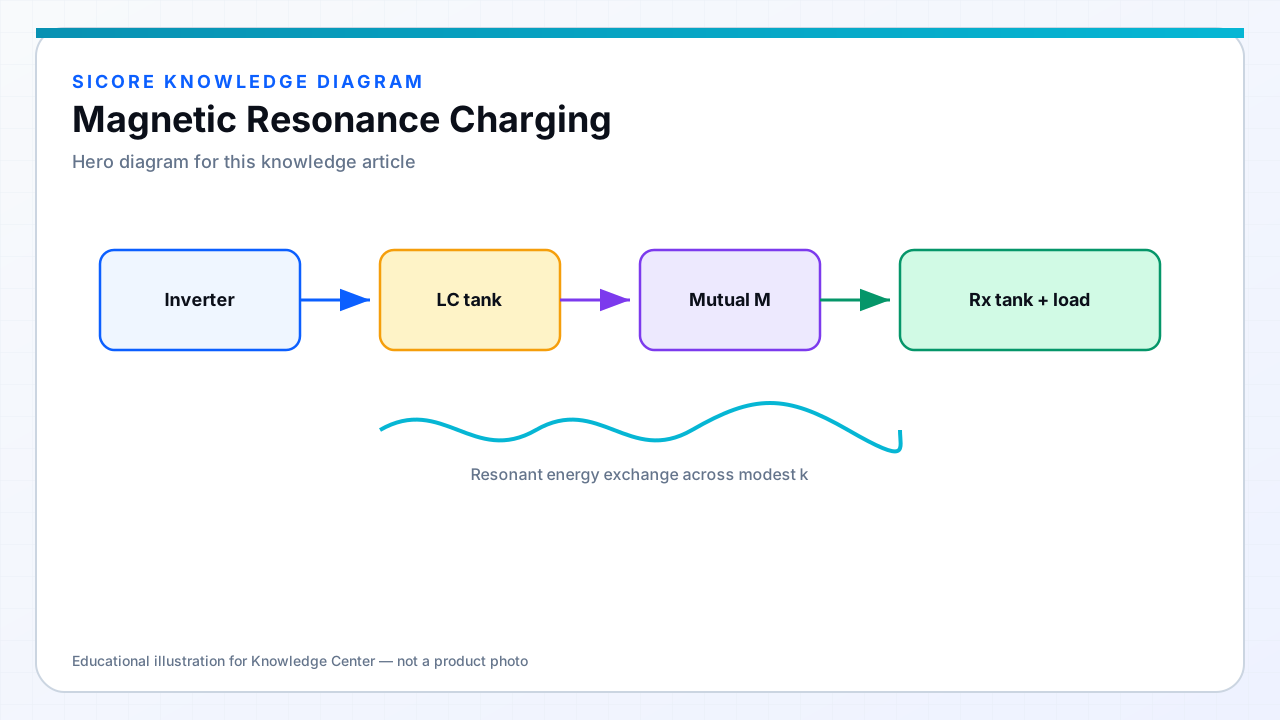
Magnetic resonance charging tunes transmitter and receiver so both operate near resonance. That raises the effective energy exchange even when the coupling coefficient is modest — useful for larger air gaps and imperfect alignment common in AGV docking and vehicle charging.
01Core ideas
- Coupling coefficient (k): how strongly the coils share flux.
- Quality factor (Q): how under-damped each resonant tank is.
- Compensation networks: capacitors (and sometimes inductors) that cancel reactive power and shape the gain curve.
- Soft switching (ZVS/ZCS): reduces switching loss at high frequency and high power.
02Where resonance helps industrial docks
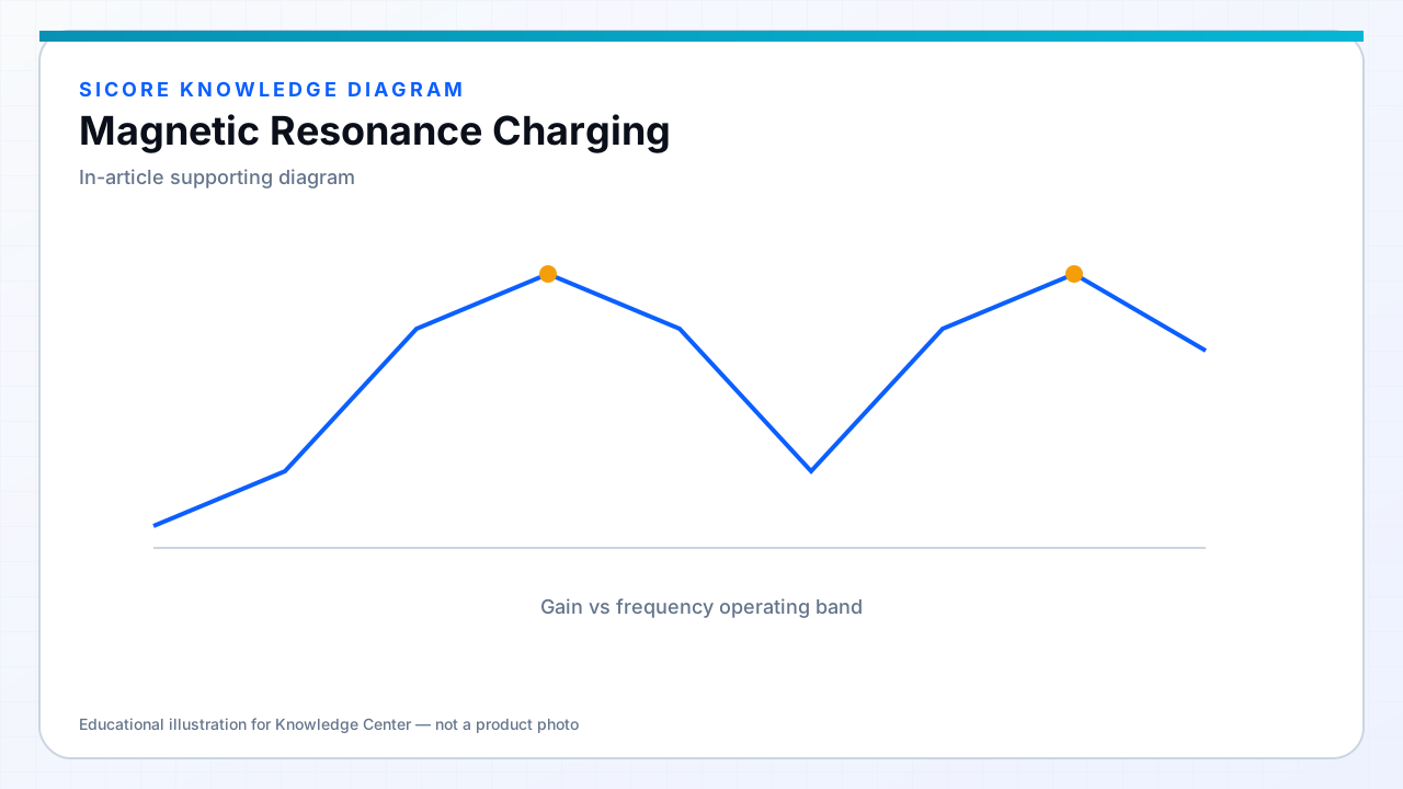
Warehouse floors, outdoor pads, and robot underbodies rarely offer perfect coil-to-coil seating. Resonance widens the usable operating window, but it also introduces frequency splitting, detuning from metal nearby, and tighter control requirements. Intelligent frequency tracking and impedance matching are often part of a production-ready resonant charger.