
Wiki article · Collection 03
Coil Aging and Reliability
Engineering reference on Coil Aging and Reliability for wireless power system design, integration, and deployment.
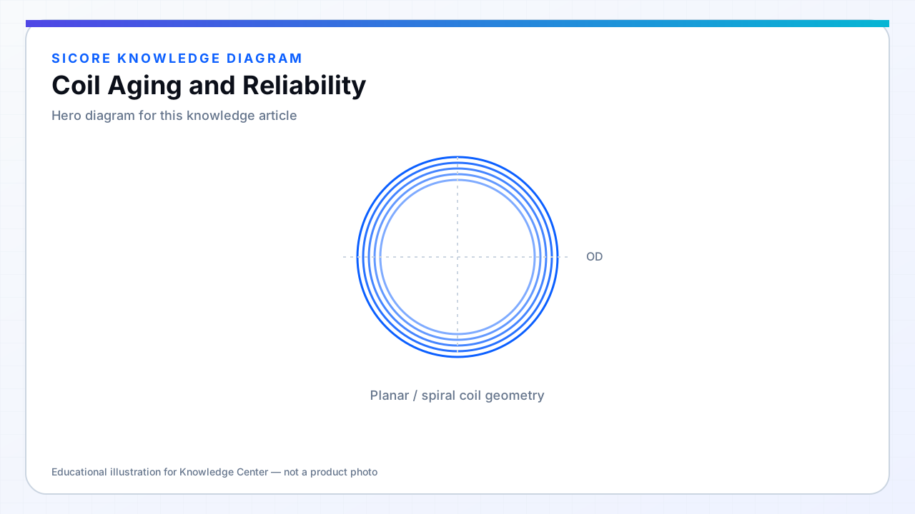
Coil aging accumulates from thermal cycling of enamel and potting, moisture ingress, ferrite micro-cracking, and terminal corrosion. AGV fleets targeting 5–10 year life need reliability models tying operating temperature, duty cycle, and environmental class to failure rates.
Silent degradation — rising Rac or falling insulation resistance — precedes catastrophic failure. Trending coil Q or charge session efficiency in telemetry catches drift early.
01Aging drivers
- Temperature: inner turn hot spots accelerate enamel crack.
- Humidity: outdoor pads and wash-down zones.
- Mechanical: vibration and docking impact cumulative.
- Chemical: oil mist, battery electrolyte mist in battery-change areas.
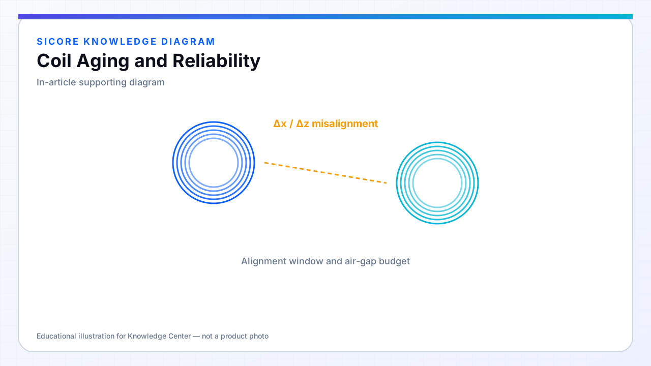
02Reliability practices
Accelerated thermal aging on samples before release. Weibull or similar life data from pilot fleets. Define end-of-life as Rac or L out of band, not only open circuit.
03Spares and rework
- Stock coil assemblies, not only full pads, if modular.
- Field replacement recalibration procedure for FOD and power limits.
- Avoid mixing old and new ferrite lot on same pad without retest.