
Wiki article · Collection 03
Coil Testing and Measurement
Engineering reference on Coil Testing and Measurement for wireless power system design, integration, and deployment.
6 minArticle 46/50Coil Design
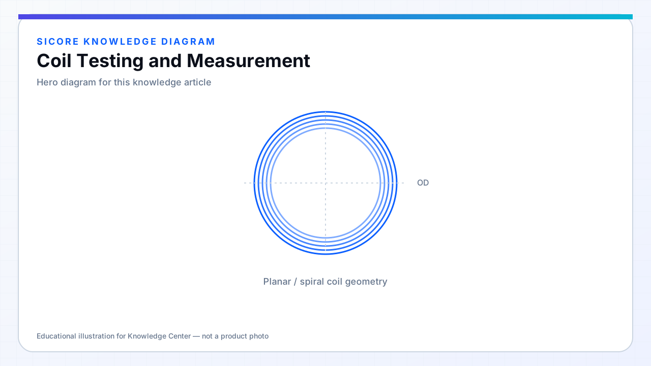
Coil testing verifies that magnetics match design before integration into pads and vehicles. Minimum production tests usually include inductance and resistance at operating frequency; qualification adds coupling maps, thermal soak, Hi-Pot, and vibration.
Fixtures must reproduce production mounting — a coil held in air by clips measures different L than when bolted to the ferrite plate.
01Core measurements
- L and Rac at f_op with defined drive level.
- Self-resonant frequency (SRF) if relevant to EMI guards.
- Q derived from L and Rac or direct network analyzer Q.
- Hi-Pot coil-to-shield and coil-to-core.
02System-level tests
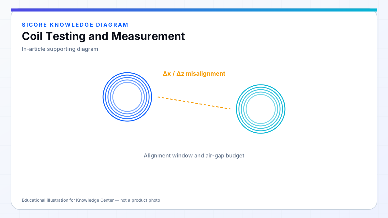
Pair TX and RX on alignment stage; measure power vs position at rated inverter settings. Include misalignment stops defined in spec. Store golden traces for serial-number traceability.
03Pass/fail philosophy
- Tight Rac control matters as much as L for thermal parity across fleet.
- Reject outliers even inside L tolerance if Q is low.
- NCR review for patterns (winding machine drift, ferrite lot).