
Wiki article · Collection 03
Impedance Analyzer Methods
Engineering reference on Impedance Analyzer Methods for wireless power system design, integration, and deployment.
6 minArticle 47/50Coil Design
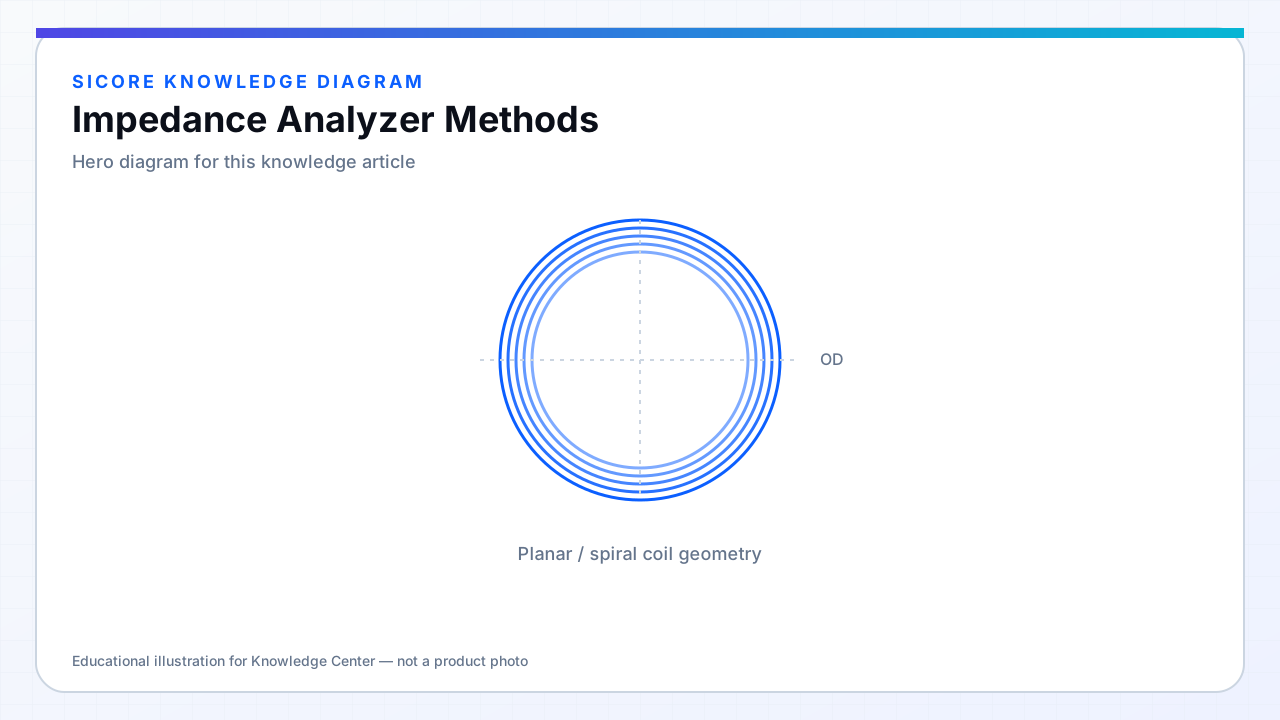
Impedance analyzers measure Z(f) = R(f) + jX(f) on coils, extracting L, Rac, and Q at the operating frequency. For coupled TX/RX, two-port S-parameter or mutual-Z methods yield k and M without full power transfer tests.
Calibration at the fixture plane removes cable and probe parasitics — critical when milliohm Rac matters.
01Single-coil measurement
- Series or parallel equivalent circuit choice documented per standard used.
- Drive level low enough to avoid ferrite heating during sweep.
- Open/short/load calibration on the production fixture.
02Coupled measurement
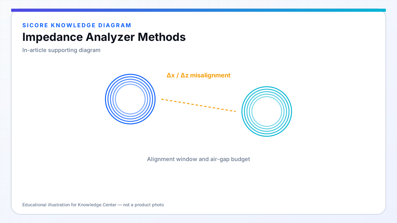
Measure L1, L2 with partner open or shorted as topology requires. Extract k from mutual inductance or from split resonance frequencies in weak coupling approximations — know when approximation breaks. Align coils on gauge blocks for repeatable gap.
03Pitfalls
- Clip leads forming loops that pick up ambient noise.
- Measuring at wrong frequency (only 1 kHz LCR meter data).
- Ignoring fixture capacitance masking SRF.