
Wiki article · Collection 03
Coil Turns Design
Engineering reference on Coil Turns Design for wireless power system design, integration, and deployment.
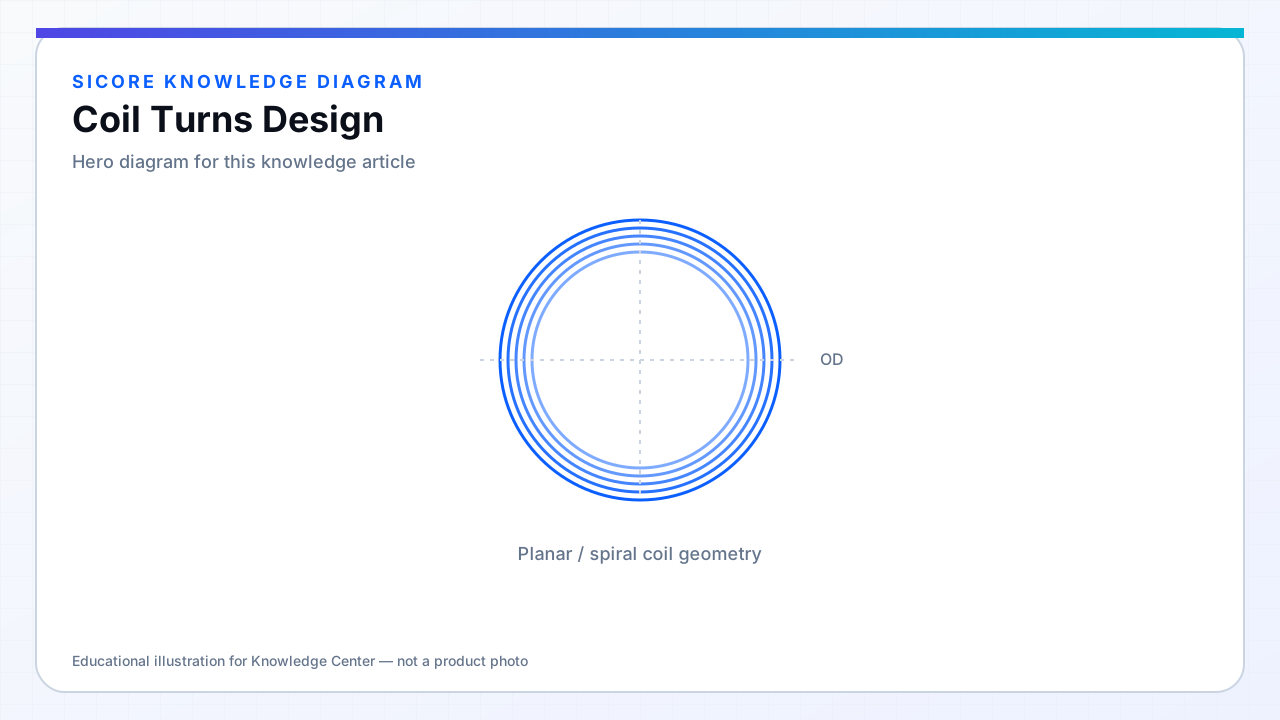
Turn count N is the primary knob for inductance in a fixed geometry, scaling roughly with N² for closely coupled turns on the same former. In resonant WPT, N also sets open-circuit voltage on the receiver, magnetizing current on the transmitter, and the distribution of AC loss across turns.
More turns are not free gain — higher N raises wire length, proximity effect, and voltage on tuning capacitors. The optimum N sits at the intersection of L target, k geometry, and loss budget.
01Design sequence
- Fix outer diameter and gap from mechanical package.
- Estimate required L from compensation topology and frequency.
- Sweep N in simulation with AC resistance model.
- Check capacitor voltage and semiconductor current at min/max k and load.
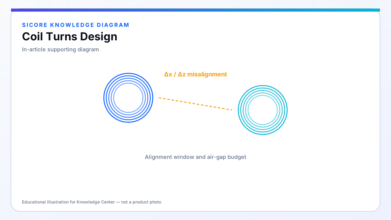
02Turn count vs fill factor
Dense turn packing increases L per area but worsens inner-turn heating. Sometimes fewer turns with larger area or ferrite delivers lower total loss than max turns in a small disc. Prototype two N values before locking ferrite tooling.
03Tolerance
- Specify L tolerance band tied to compensation capacitor selection.
- Turn count errors from skipped turns in winding are catastrophic — use turn counters.
- Potting compression can slightly reduce L — include in worst-case tuning.