
Wiki article · Collection 03
Coil Pitch and Spacing
Engineering reference on Coil Pitch and Spacing for wireless power system design, integration, and deployment.
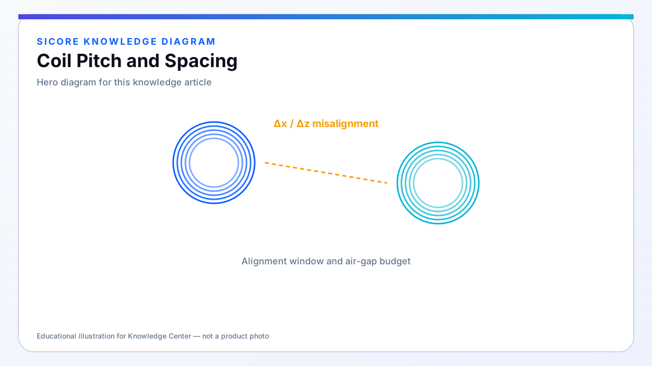
Pitch is the center-to-center spacing between adjacent turns; spacing is the physical gap between conductors. Together they set fill factor, inter-turn capacitance, and how aggressively proximity effect couples neighboring turns. Tight pitch raises L per unit area but concentrates loss in inner regions.
PCB coils define pitch by trace width plus gap; litz spirals use spacers or bobbin grooves. Inconsistent pitch from hand winding shows up as L scatter across production.
01Electrical effects
- Closer spacing increases inter-turn capacitance, lowering self-resonant frequency.
- Wider spacing reduces proximity loss but needs more turns or larger diameter for same L.
- Non-uniform spacing creates local field hotspots and uneven heating.
02Practical guidance
Follow vendor recommendations for minimum spacing in potting compounds to avoid corona and partial discharge at high receiver voltages. For high-power TX coils, prioritize uniform spacing over maximum fill — hot spots derate the whole pad.
03Inspection
- Optical or AOI on PCB gaps before potting.
- Sample cross-section of potted litz spirals in NPI.
- Compare Q across builds — Q drop often traces to spacing collapse.