
Wiki article · Collection 03
Inner and Outer Diameter
Engineering reference on Inner and Outer Diameter for wireless power system design, integration, and deployment.
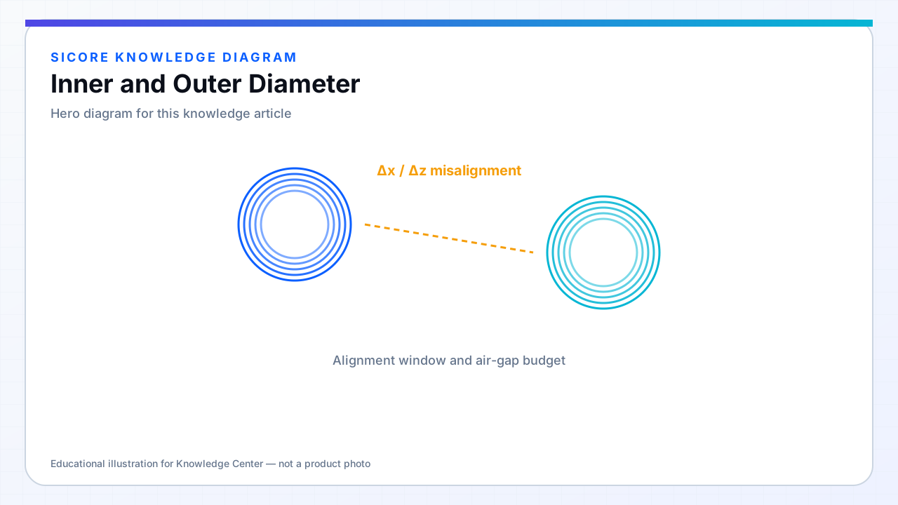
For planar spirals, OD sets the active coupling area seen by the partner coil while ID clears central hardware (alignment pins, bolts, cable exits) and shapes the inner turn density. Increasing OD with fixed turns raises L and k potential; increasing ID hollows the center and removes inner high-loss turns but reduces L per turn.
Industrial pads often maximize OD within floor tile standards while keeping ID large enough for mechanical stack and ferrite tile arrangement.
01OD trade-offs
- Larger OD: better k, more copper, higher leakage to pad edges.
- Smaller OD: fits tight spaces, requires higher current or frequency for same power.
- OD mismatch between TX and RX when RX is smaller caps achievable k.
02ID trade-offs
Small ID concentrates many inner turns with high AC loss. Large ID without adjusting turns drops L — may require ferrite or more outer turns. Center hole sometimes hosts permanent magnets for alignment — verify they do not saturate ferrite or bias FOD sensors.
03Documentation
- Specify OD/ID relative to pad housing datum, not coil copper edge alone.
- Include encapsulation overhang in floor tile cutout drawings.
- Fleet replacement pads must match OD/ID within tolerance or re-commission k map.