
Wiki article · Collection 03
Self-Inductance Design
Engineering reference on Self-Inductance Design for wireless power system design, integration, and deployment.
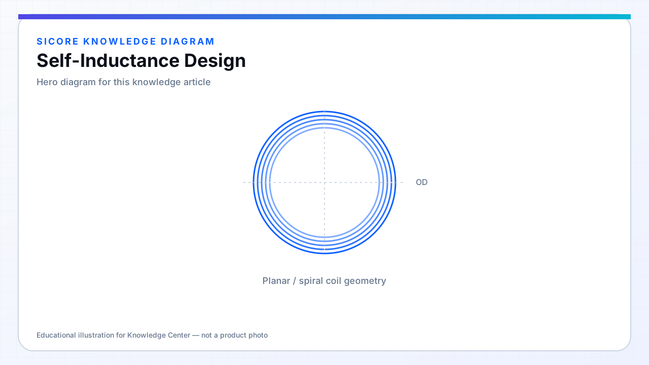
Self-inductance L characterizes energy stored in the coil's own magnetic field per ampere. In WPT, L appears in resonant frequency formulas, impedance matching, and soft-switching conditions. Transmitter and receiver each carry an L that must pair with tuning capacitors C to hit the operating band and stay there under misalignment.
L is not constant in operation — ferrite saturation, nearby metal, and temperature change L by percents that matter to high-Q systems.
01Setting L targets
- Derive from chosen topology (series/parallel/LCC) and operating frequency.
- Include margin for ± capacitance tolerance and L drift over temperature.
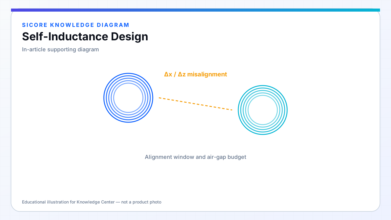
- Verify L at min and max gap, not only nominal.
02Measurement
Use impedance analyzer at operating frequency with coil in final potting and ferrite configuration. Open-short-load calibration on the fixture. Document test frequency and amplitude — L can vary slightly with drive level near saturation.
03Adjustment methods
- Turn count change (production-friendly if planned).
- Ferrite shims or tile removal (last resort in field).
- Switchable compensation banks on the PCB (control complexity).