
Wiki article · Collection 03
Misalignment
Engineering reference on Misalignment for wireless power system design, integration, and deployment.
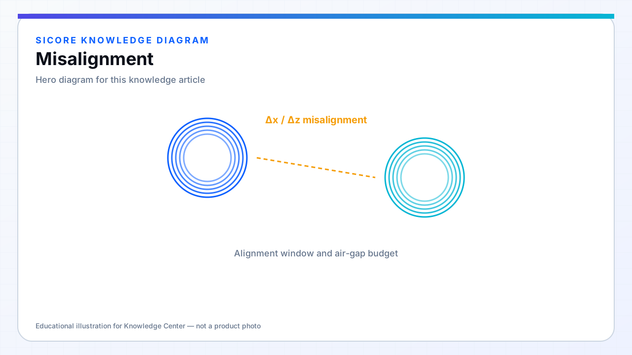
Misalignment is any deviation from nominal coil registration: lateral shift, air-gap change, or rotation. Each mode reduces overlapping flux and shifts the impedance seen by the inverter. Resonant systems may remain efficient at moderate misalignment if compensation and control track the detuning; non-resonant or poorly tuned systems fall off sharply.
Fleet data often shows a distribution, not a single worst case — design for the 95th percentile stop error, not only perfect alignment.
01Coupling impact
- Lateral offset: typically the dominant issue on flat docks.
- Gap increase: lowers k roughly with cube of distance for similar-sized coils (geometry-dependent).
- Yaw rotation: asymmetric coils (DD, rectangular) degrade differently by angle.
- Combined errors: superposition is not linear — test the full map.
02Mitigation hierarchy
First improve mechanical repeatability and coil geometry (DD, arrays). Then widen control bandwidth and compensation tuning. Last resort: accept lower power or longer charge time under misalignment — but specify that explicitly in SLA documents so operators understand throughput impact.
03Testing protocol
- Automated XY stage sweeps at nominal gap before field deployment.
- Include steel plate under vehicle to mimic real flux paths.
- Log inverter phase, current, and thermal limits at each grid point.