
Wiki article · Collection 03
Coil Alignment
Engineering reference on Coil Alignment for wireless power system design, integration, and deployment.
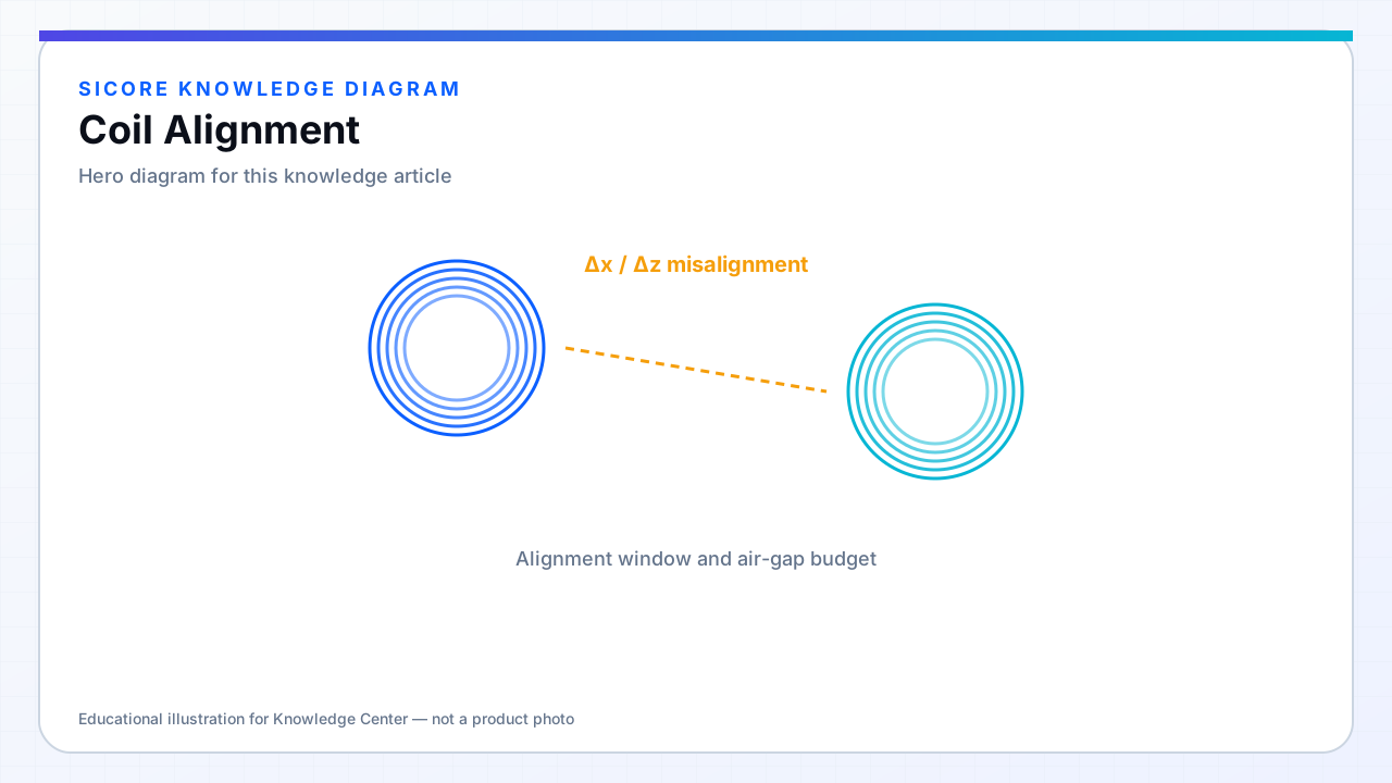
Coil alignment is the physical registration of transmitter and receiver windings so coupling stays within the designed k window. Wireless power cannot fully software-correct a coil that is centimeters out of overlap — alignment is a mechanical, sensing, and sometimes active guidance problem.
Industrial docks combine mechanical guides (cones, V-grooves, floor markers), vehicle positioning (LiDAR, magnetic tape), and coil-centric features (ferrite pegs, asymmetric pad shapes) to repeat alignment across thousands of cycles.
01Alignment specifications
- Define allowable offset (X, Y), gap (Z), yaw, pitch, roll for full power.
- Separate 'charge OK' from 'full power' zones for fleet analytics.
- Include wear: guide roller diameter shrinkage shifts stop position over years.
02Coil-level tactics
Shape the pad and receiver footprints so gross misalignment is visually obvious during install. Use asymmetric bolt patterns to prevent 180° rotation errors. Document coil center relative to mechanical datums on drawings — installers align housings, not copper.
03Verification
- Golden vehicle or fixture with known coil position for end-of-line pad test.
- k or received open-circuit voltage map vs position for commissioning records.
- Periodic re-check after floor maintenance or pad replacement.