
Wiki article · Collection 03
Magnetic Shielding
Engineering reference on Magnetic Shielding for wireless power system design, integration, and deployment.
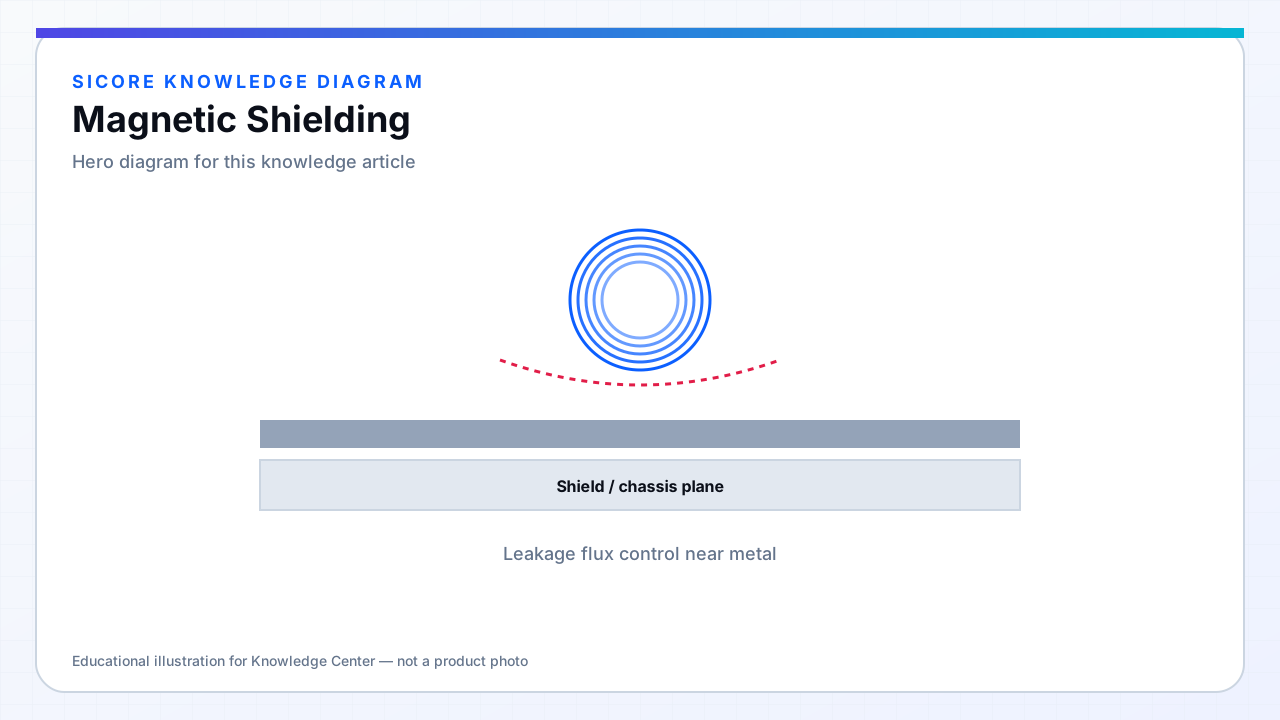
Magnetic shielding in WPT redirects leakage flux away from sensitive areas: vehicle electronics, steel frames, operator-accessible surfaces, and neighboring pads. Shields may be ferrite back-plates, aluminum or copper plates (eddy-current shields), or laminated silicon steel depending on frequency and loss budget.
A shield always interacts with the coil — it lowers self-inductance, changes k, and can add loss if conductive shields are too close or too thick without analysis.
01Shield types
- Ferrite back-plate: guides flux, adds inductance, limited saturation headroom.
- Conductive sheet: reflects flux via eddy currents; frequency-dependent penetration depth.
- Hybrid ferrite + aluminum: common in receivers to protect battery enclosure electronics.
02Design rules
Place shields on the non-coupling side of the coil when possible. Maintain minimum air gaps between coil and conductive shield to control capacitance and loss. Validate with and without the vehicle chassis present — the dock alone is not the full system.
03Failure modes
- Saturated ferrite shield acts like air suddenly — detuning during high-power sessions.
- Loose steel shields vibrating in the field — audible noise and intermittent loss.
- Corrosion or fasteners penetrating shield continuity creating slot antennas.