
Wiki article · Collection 03
Potting and Encapsulation
Engineering reference on Potting and Encapsulation for wireless power system design, integration, and deployment.
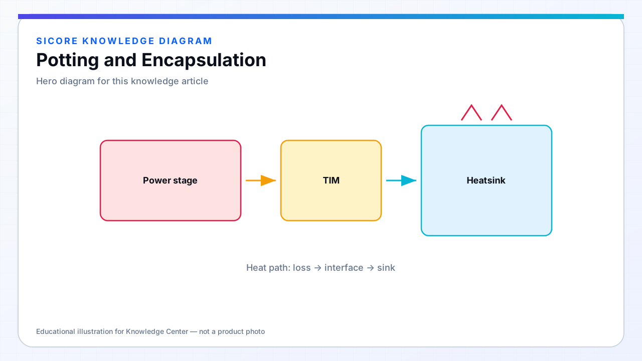
Potting fixes coil geometry against vibration, excludes moisture, and provides dielectric separation. Encapsulation is the outer mechanical shell seen by the dock environment. Both alter effective permittivity around conductors (shifting inter-turn capacitance and L slightly) and define thermal paths.
Wrong potting viscosity traps voids under litz bundles — partial discharge and hot spots follow. Cure exotherm on large pads can stress ferrite if batch size is uncontrolled.
01Material properties
- Thermal conductivity (W/m·K) vs cost and flowability.
- Hardness and CTE match to ferrite and aluminum to reduce cracking.
- Dielectric constant affecting self-resonance and Hi-Pot paths.
- Flammability and UL ratings for floor-installed equipment.
02Process control
Vacuum degas for high-voltage receivers. Mold fixturing maintains flatness for floor tiles. Record batch, cure time, and temperature. Re-measure L and SRF on potted units — accept/reject limits may differ from bare coil.
03Serviceability
- Potting is often non-repairable — modular coil inserts ease field swap.
- Document potting removal as destructive if applicable.
- Color and surface finish affect IR thermography calibration for diagnostics.