
Wiki article · Collection 04
Buck-Boost Converter
Engineering reference on Buck-Boost Converter for wireless power system design, integration, and deployment.
6 minArticle 23/50Power Electronics
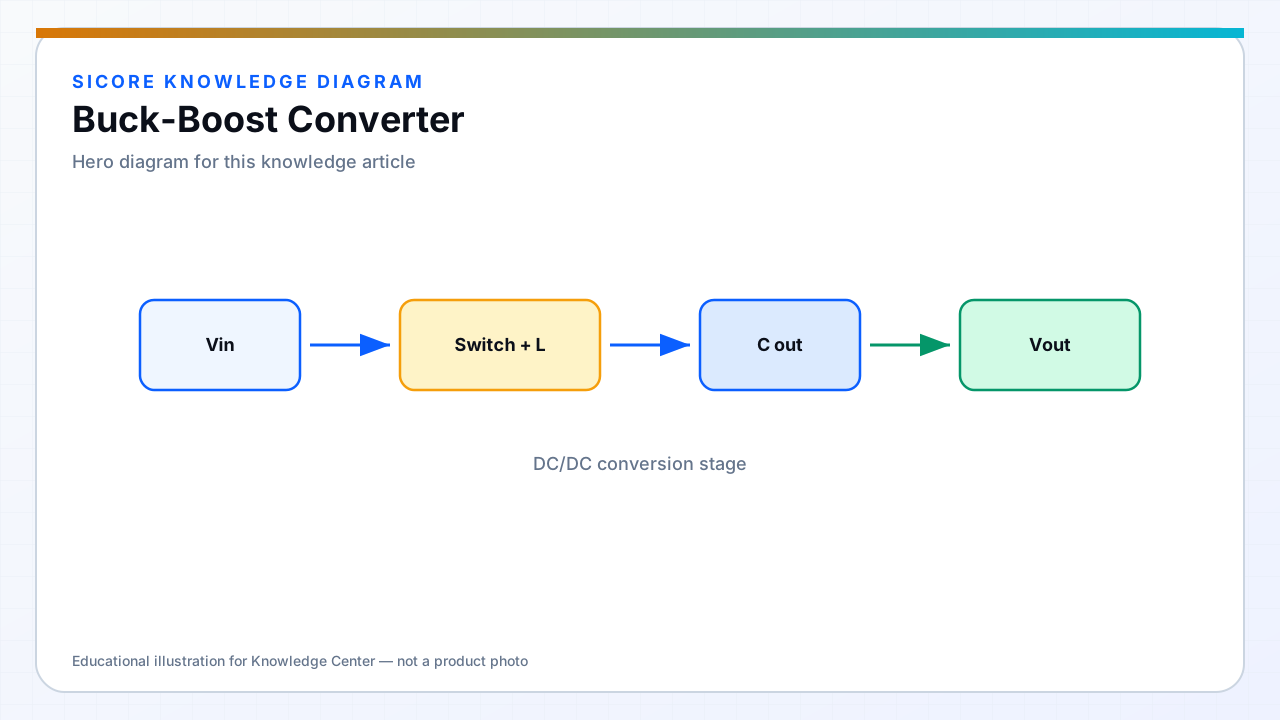
Buck-boost topologies handle inputs both above and below the output — useful on AGVs when coil voltage swings with misalignment and load. Four-switch buck-boost avoids the inverted ground reference of classic inverting buck-boost.
Complexity trades against a simpler buck with wider input range and link power control limiting low-voltage episodes.
01When needed
- Wide battery voltage range (e.g., empty to full SOC) with fixed coil tuning.
- Ultracap buffers with voltage swing distinct from pack voltage.
- Dock internal rails from variable PFC bus during brownout.
02Control
Mode transitions between buck and boost regions need hysteresis or unified control to avoid oscillation. Efficiency dips near buck-boost boundary — map loss there explicitly in efficiency charts shown to customers.
03Alternatives
- Resonant frequency or phase control on transmitter to keep receiver voltage in buck-only range.
- Series regulating element when efficiency penalty is acceptable for simplicity.