
Wiki article · Collection 04
LLC Resonant Converter
Engineering reference on LLC Resonant Converter for wireless power system design, integration, and deployment.
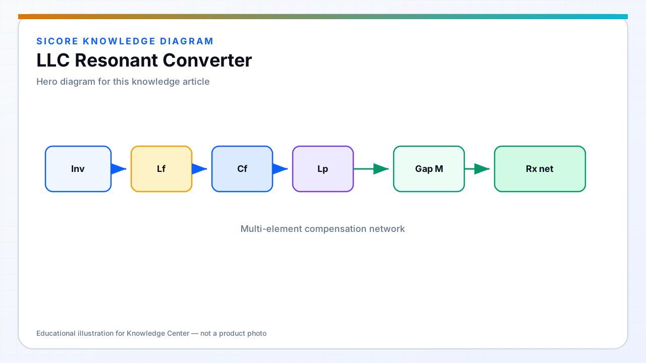
LLC converters use a series inductor, parallel inductor, and capacitor resonant network — often with a transformer — to achieve high efficiency through zero-voltage switching on the primary switches. They appear as isolated auxiliary supplies or intermediate stages in large dock power cabinets.
Gain varies with frequency; design the magnetizing inductance and turns ratio for the required bus and load range.
01Benefits
- ZVS on primary over a useful load range reduces switching loss.
- Low output ripple with proper secondary filter.
- Galvanic isolation for safety partitions inside the dock controller.
02Design challenges
LLC gain curve is narrow — input voltage and load spread must fit the chosen region. Transformer leakage and Lm split affect resonance. Starting into pre-biased output caps on connected vehicles requires careful sequencing.
03Relation to WPT
- Distinct from the WPT coil resonator — do not conflate two different LLC networks in one system diagram without clear labels.
- Housekeeping LLC noise must not corrupt WPT current sensing grounds.