
Wiki article · Collection 04
Buck Converter
Engineering reference on Buck Converter for wireless power system design, integration, and deployment.
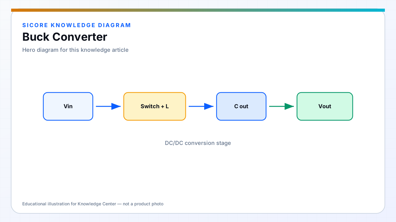
A buck converter steps voltage down by switching an inductor between input and output with a ground-referenced switch. On vehicles, bucks regulate WPT rectifier output to battery charge voltage when the coupled voltage exceeds what the pack needs.
Continuous conduction mode bucks at fixed frequency are well understood — input and output capacitor RMS current and inductor ripple must be sized for wireless load steps.
01WPT use cases
- Battery charging regulator after synchronous rectifier.
- 24 V or 12 V auxiliary from higher traction voltage on AMRs.
- Dock internal housekeeping from the PFC bus.
02Design notes
Synchronous buck for efficiency at charge current. Watch light-load operation when AGV finishes charge — some bucks enter pulse skipping that can interact with BMS measurements. Input cap must handle pulse current from both WPT ripple and buck switching.
03Integration
- Coordinate enable with WPT power availability to avoid inrush.
- Place inductor away from receiver coil flux if core is unshielded.
- Current limit aligned with wireless link power cap.