
Wiki article · Collection 04
Class-D Amplifier Stages
Engineering reference on Class-D Amplifier Stages for wireless power system design, integration, and deployment.
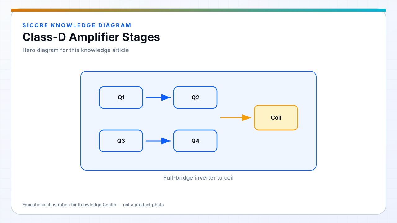
Class-D amplification means high-efficiency switching output stages with filtered or resonant load paths — the same conceptual bucket as most WPT transmitters. The coil tank often provides the filtering; the inverter switches at high efficiency while the resonator selects fundamental power delivery.
Understanding Class-D helps debug distortion-like artifacts when control resolution, dead time, or modulation limits create unwanted harmonics in coil current.
01Parallels to WPT
- Switching stage plus LC filter equals resonant power delivery.
- Modulation (PWM, phase, frequency) sets effective coil voltage.
- Loop bandwidth and stability matter for load transients on the receiver.
02Differences from audio
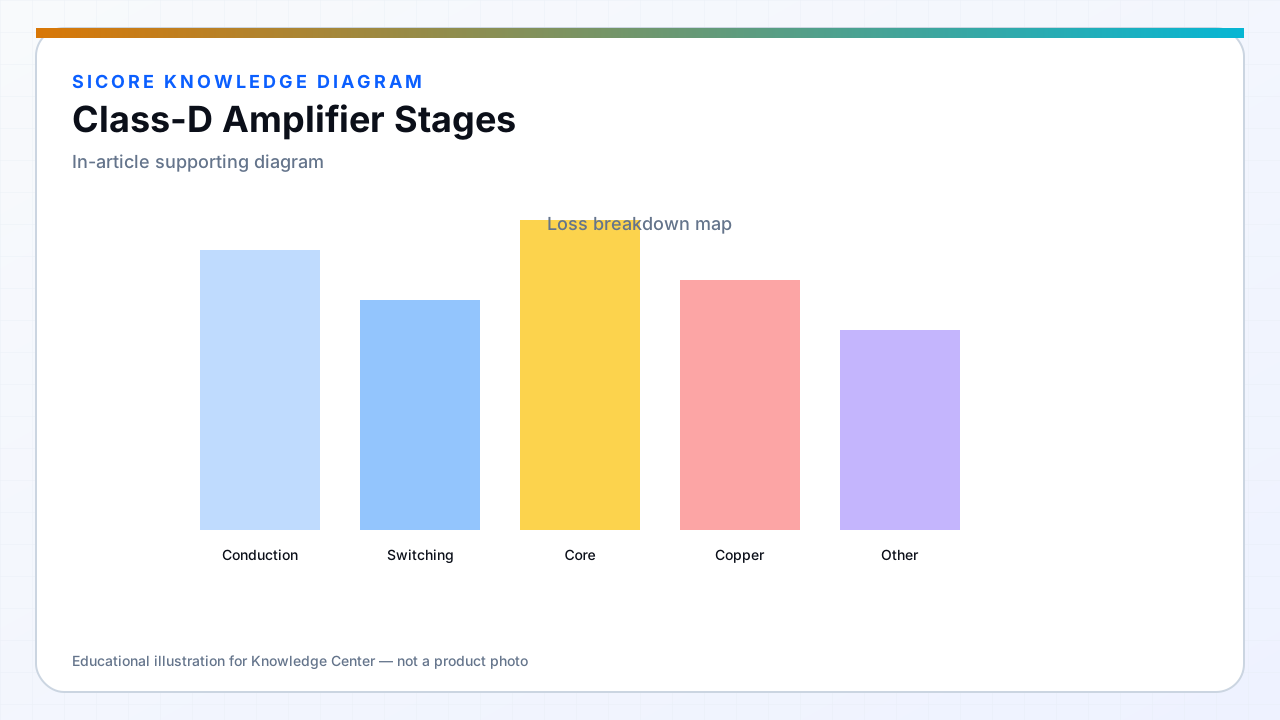
Power levels and currents far exceed audio Class-D. Magnetics are the functional load, not a speaker voice coil. Safety, isolation, and EMC dominate — not THD to the ear. Still, spectral content of coil current affects loss and EMI similarly to harmonic distortion in amplifiers.
03Practical use
- Borrow Class-D driver IC concepts cautiously — WPT needs higher voltage and current.
- Simulate harmonic content under phase modulation used for power control.
- Do not confuse marketing “Class-D wireless” with a specific standard topology.