
Wiki article · Collection 04
Half-Bridge Inverter
Engineering reference on Half-Bridge Inverter for wireless power system design, integration, and deployment.
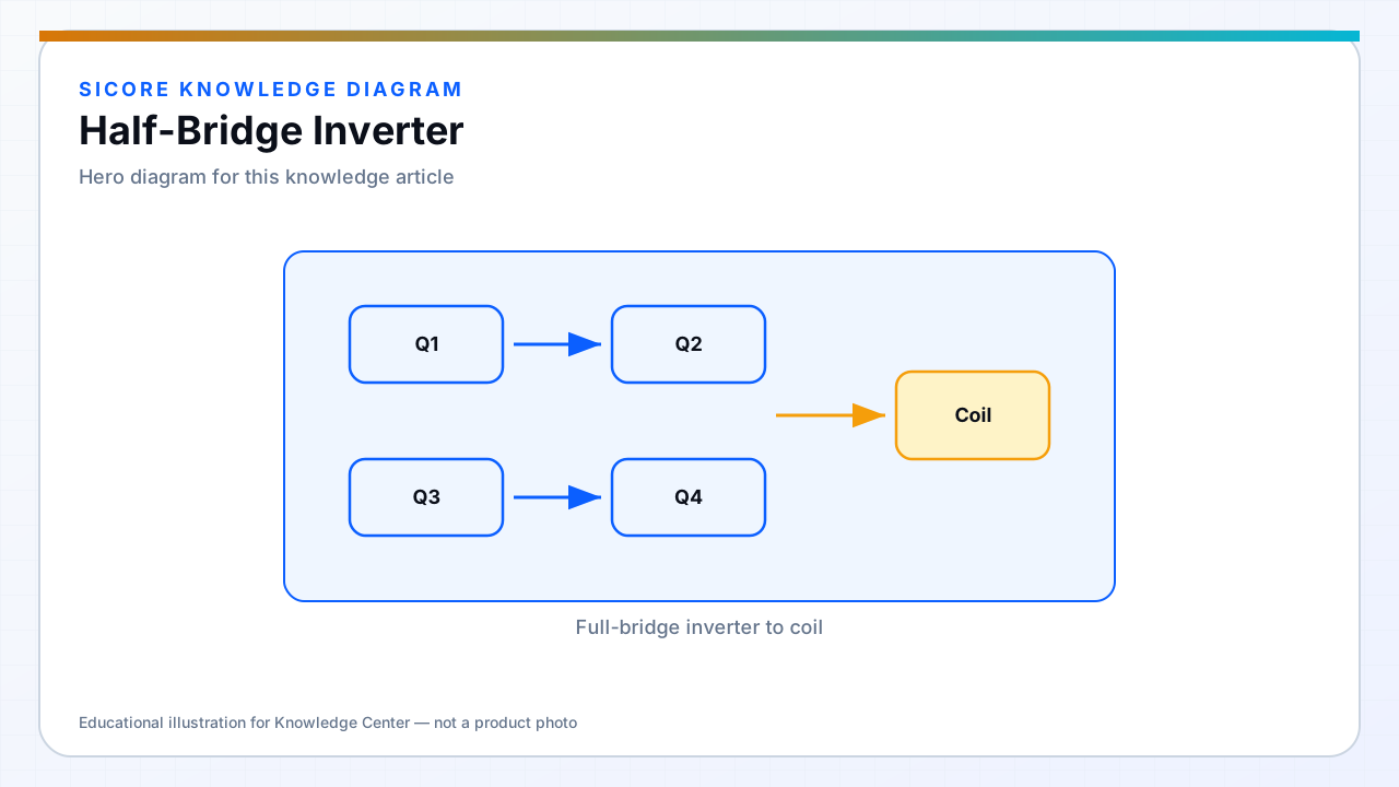
A half-bridge places two switches in series across the DC bus with the load connected from the midpoint to ground or to a second midpoint in a split-cap topology. It applies half the bus voltage to the tank in simple PWM, making it attractive for compact and cost-sensitive charging modules.
Half-bridge designs need a stable midpoint — often two bulk capacitors — and careful balance to avoid DC bias in the transformer or coil series path.
01Strengths
- Fewer switches and drivers than full-bridge.
- Natural fit for symmetric resonant tanks with split capacitors.
- Widely used in mid-power consumer and industrial WPT where bus voltage can be raised.
02Challenges
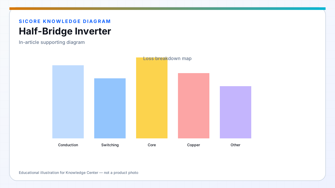
Same coil current requires higher peak tank voltage or higher bus than full-bridge. Midpoint capacitor RMS current can heat smaller caps. Bootstrap high-side drive limits duty cycle and refresh timing — validate at minimum pulse width used for control.
03Dock fit
- Pedestal chargers under roughly 3–5 kW when thermal and voltage budget allow.
- Modules paralleled for lane charging with synchronized control.
- Receiver-side half-bridge active rectifiers in related topologies — similar layout rules.