
Wiki article · Collection 04
Full-Bridge Inverter
Engineering reference on Full-Bridge Inverter for wireless power system design, integration, and deployment.
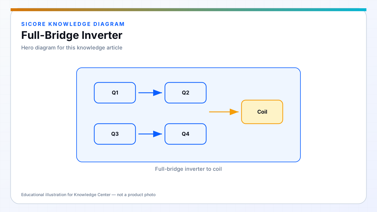
A full-bridge inverter uses four switches across the DC bus to apply positive, negative, or zero voltage to the load network. For wireless charging docks, it offers full bus utilization and flexible phase control for resonant tanks compared with a half-bridge at the same bus voltage.
The cost is more switches, more gate drive, and a layout with two switching nodes or a carefully routed single output — loop inductance in the bridge legs directly affects EMI and loss.
01WPT advantages
- Higher fundamental voltage for a given DC bus — useful for high coil current.
- Phase-shift and frequency control options for LLC and similar topologies.
- Better suited to multi-kW industrial docks than half-bridge at equal device stress.

02Design focus
Balance leg inductance so current shares between diagonal pairs. Decouple high-side and low-side drivers with clean bootstrap or isolated supplies. Verify shoot-through protection and dead time across production spread.
03When half-bridge suffices
- Lower power classes with headroom on bus voltage.
- Cost-sensitive deployments with acceptable higher current in the tank.
- Topologies that intentionally use half-bridge for symmetry with split DC link.