
Wiki article · Collection 04
Common-Mode Chokes
Engineering reference on Common-Mode Chokes for wireless power system design, integration, and deployment.
6 minArticle 38/50Power Electronics
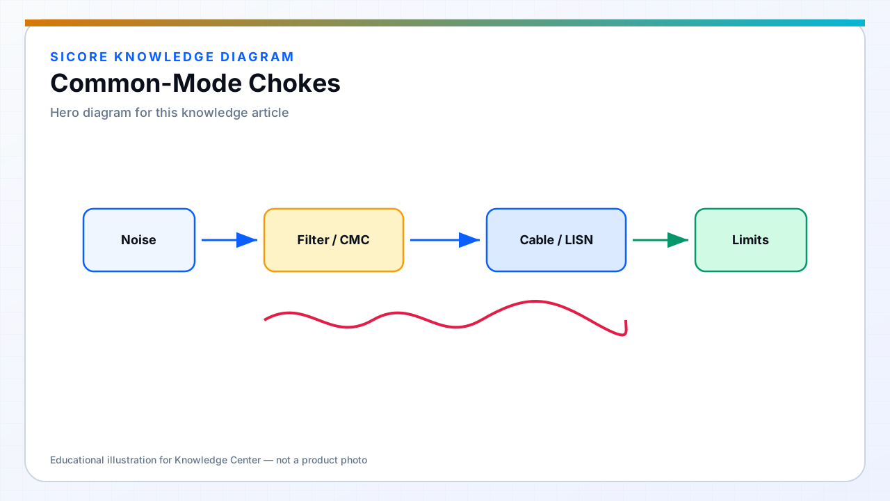
Common-mode chokes use coupled windings so equal currents on line and return cancel flux in the core, while common-mode currents see high inductance. They are central to both AC input filters and DC output filters on long cables from pedestal to floor pad.
Core material sets effective bandwidth — nanocrystalline and ferrite mixes dominate industrial EMI.
01Design parameters
- Inductance at target frequency band for standard being tested.
- Saturation current if differential imbalance exists under fault.
- Inter-winding capacitance limiting high-frequency performance.
02WPT cable routing
DC feeds to floor pads should pair positive and negative conductors through the same CM choke when emissions on long buried cables fail limits. Coil leakage can drive common-mode on DC — chokes at both ends may be needed.
03Pitfalls
- Mounting steel screws through choke cores can shift L and saturate locally.
- Parallel chokes without design intent can resonate — one designed stage preferred.