
Wiki article · Collection 04
Current-Fed Converters
Engineering reference on Current-Fed Converters for wireless power system design, integration, and deployment.
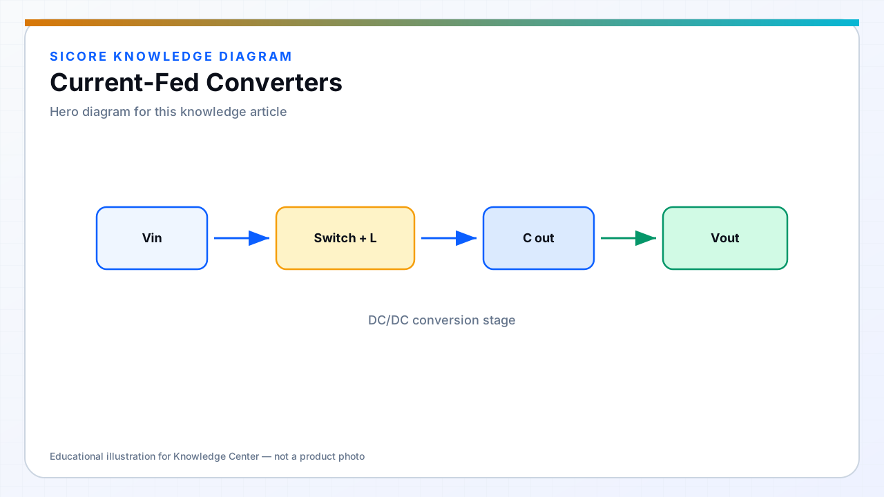
Current-fed topologies place an inductor in series with the DC input so the bridge sees approximately constant current. For WPT, that can limit fault current during receiver short and provide a natural match to some resonant tank excitations.
Open-circuit or high-impedance receiver conditions produce high voltage at the inverter output — clamping and overvoltage protection are mandatory.
01Advantages
- Inherent limit on shoot-through current during bridge faults.
- Can simplify some series-resonant WPT architectures.
- Useful when multiple receivers detune the tank unpredictably.

02Risks
Voltage spikes when coupling drops suddenly — AGV leaving dock mid-power. Input inductor saturation during asymmetric switching must be prevented. Control bandwidth differs from voltage-fed designs — retune power loops accordingly.
03Application fit
- Specialized high-power docks with defined OV clamp strategy.
- Research platforms — less common in standard AGV products than voltage-fed.
- Pair with active clamp or SAED networks when literature topology demands it.