
Wiki article · Collection 04
DC Link Capacitors
Engineering reference on DC Link Capacitors for wireless power system design, integration, and deployment.
6 minArticle 36/50Power Electronics
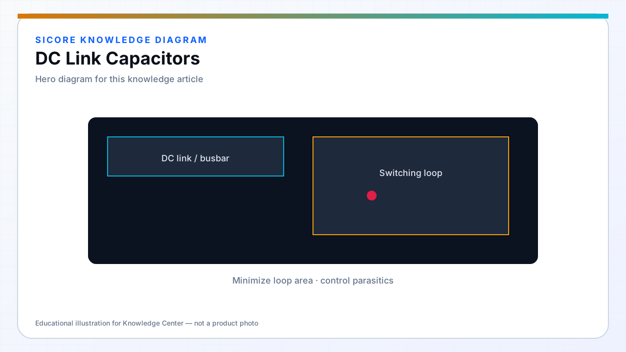
DC link capacitors absorb switching ripple and supply pulse current when the inverter draws from the bus. In WPT, pulse frequency includes switching frequency and beat components from load modulation — RMS current in caps can exceed naive estimates.
Capacitor failure in a sealed floor pad is expensive — derate voltage and temperature aggressively.
01Types
- Aluminum electrolytic for bulk energy — watch ripple current rating and life hours.
- Film capacitors for high ripple and failure mode safety in some designs.
- Ceramic multi-layer at switch terminals for high-frequency current loops.
02Placement
Minimize loop from cap terminals through switches and back. Multiple small ceramics often outperform one distant bulk cap for switching loop alone — bulk still needed for low-frequency energy.
03Aging
- Monitor bus ripple increase as ESR rises over years.
- Replace caps on preventive schedule in 24/7 AGV lanes.
- Venting electrolytics require mechanical clearance in pad design.