
Wiki article · Collection 04
DC Bus Design
Engineering reference on DC Bus Design for wireless power system design, integration, and deployment.
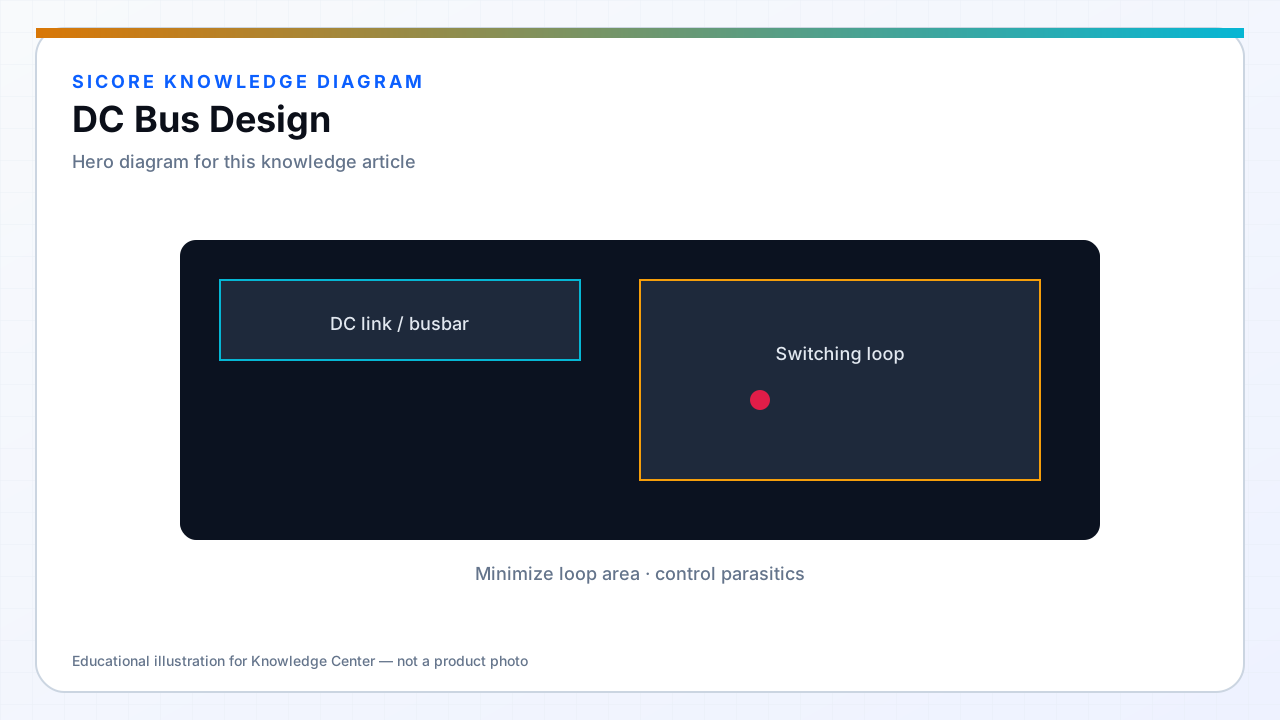
The DC bus is the energy reservoir and voltage reference for the WPT inverter. Bus voltage choice trades semiconductor stress, coil current capability, and compatibility with facility power conversion. Industrial docks commonly use 400 V class or lower for smaller pedestals.
Bus design includes capacitors, pre-charge, fusing, discharge resistors, and distribution impedance to multiple inverter modules in lane configurations.
01Capacitor bank
- Bulk electrolytic for energy storage; film and ceramic for high-frequency ripple.
- ESR and ESL low enough that ripple does not modulate coil current detectably.
- Life rating for ambient inside pad — not 105 °C datasheet at 25 °C enclosure.
02Safety and service
Pre-charge limits inrush when connecting to PFC or battery backup. Bleeder resistors or active discharge for technician safety after shutdown — with lockout verification. Clear labeling of bus voltage on enclosures.
03Multi-module docks
- Symmetric bus bars so paralleled inverters share current.
- Local cap at each module plus central bulk — model both.
- Isolate faulty module without collapsing entire lane bus.