
Wiki article · Collection 04
Shoot-Through Protection
Engineering reference on Shoot-Through Protection for wireless power system design, integration, and deployment.
6 minArticle 34/50Power Electronics
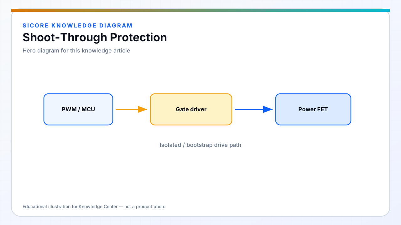
Shoot-through is a direct short across the DC bus through two switches in the same leg. Energy release is fast — enough to fuse bond wires or trip breakers. Wireless charging docks need layered protection because firmware bugs, noise, or brownout recovery can corrupt PWM commands.
Protection combines dead time, driver interlocks, hardware desat detection, and supply monitoring.
01Hardware layers
- Gate driver interlock preventing overlapping outputs.
- Desaturation detection turning off switch on abnormal VDS.
- Fast fuse or breaker coordination — know let-through energy.
02Firmware layers
Complementary PWM with enforced blanking interval. Safe state on fault — all gates off. Watchdog and clock failure must default to off, not last PWM pattern.
03Commissioning
- Intentionally marginal dead time on engineering unit to verify detection — not in field.
- Never bypass interlocks for “more power” experiments.
- Log shoot-through fault codes to fleet management for recurring dock IDs.