
Wiki article · Collection 04
Efficiency Mapping
Engineering reference on Efficiency Mapping for wireless power system design, integration, and deployment.
6 minArticle 45/50Power Electronics
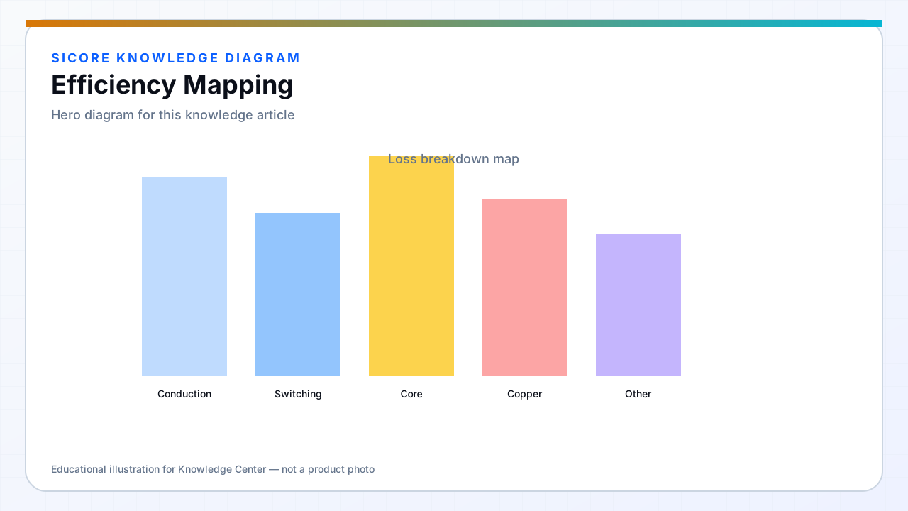
Efficiency mapping builds a surface of input to output power ratio versus load, coupling, and environmental conditions. Customers compare wireless to conductive charging on kWh cost — maps must include PFC, inverter, coil, rectifier, and post-regulation.
Single-point peak efficiency marketing misleads fleet operators whose robots charge at partial alignment daily.
01Measurement setup
- Precision power analyzers on AC input and DC output to battery.
- Defined alignment fixtures for min, nominal, max k positions.
- Soak until thermal steady state before recording each point.
02Presentation
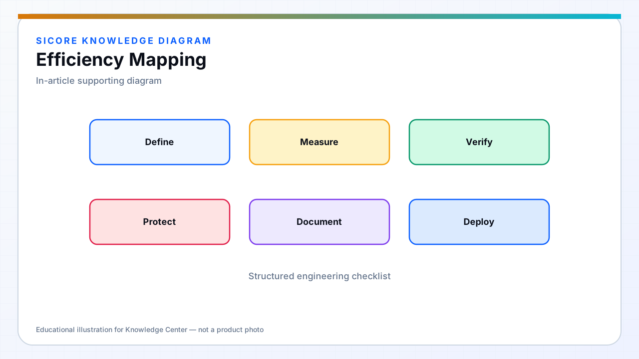
Contour plots of efficiency versus power and misalignment. Separate maps for ambient temperature corners if derating is significant. Include idle and standby loss for opportunity charging duty cycles.
03Use in product
- Set transmitter power limits where efficiency drops below business threshold.
- Guide coil redesign priorities from loss breakdown at worst map corner.