
Wiki article · Collection 04
Loss Breakdown Analysis
Engineering reference on Loss Breakdown Analysis for wireless power system design, integration, and deployment.
6 minArticle 46/50Power Electronics
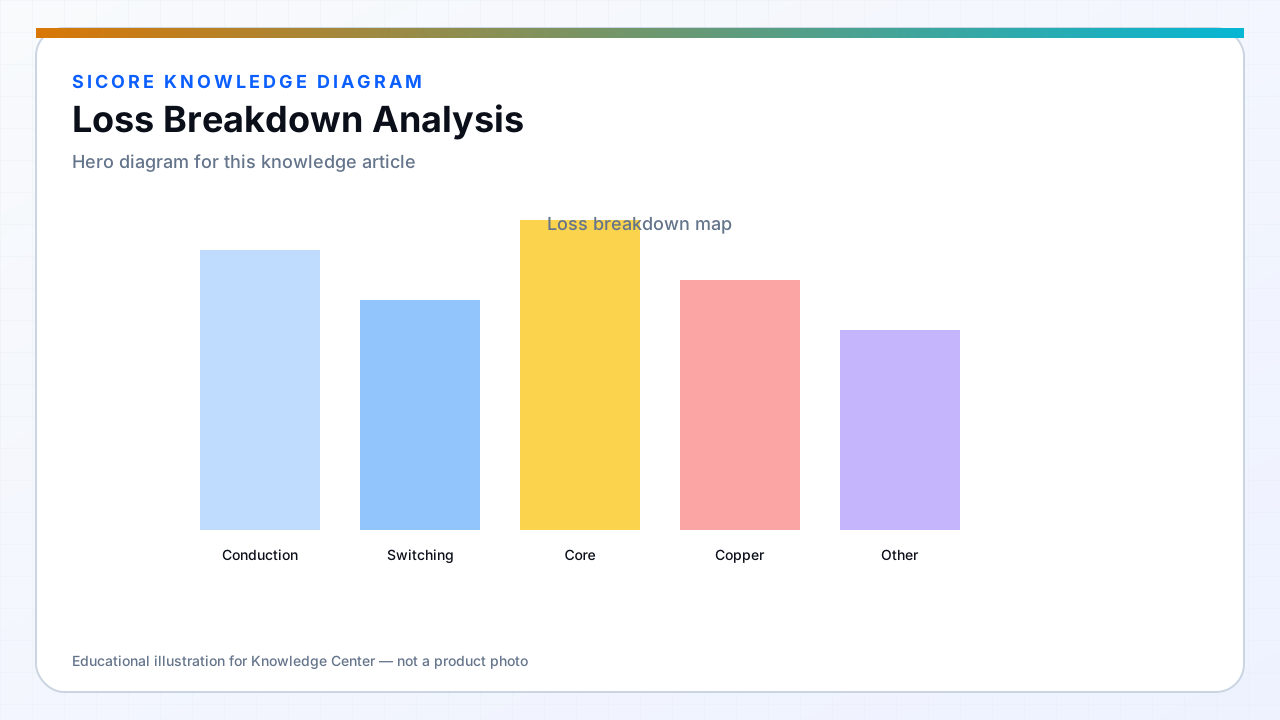
Loss breakdown analysis assigns watts to each subsystem so improvement efforts target the largest contributors. Methods include calorimetry, electrical calculation from measured waveforms, and incremental substitution of known-efficient components.
Without breakdown, teams over-optimize switching loss while conduction loss dominates at fleet operating point.
01Categories
- PFC and input filter loss.
- Inverter switching and conduction loss.
- Coil copper and ferrite core loss.
- Receiver rectifier or SR loss.
- Control and auxiliary supply overhead.
02Process
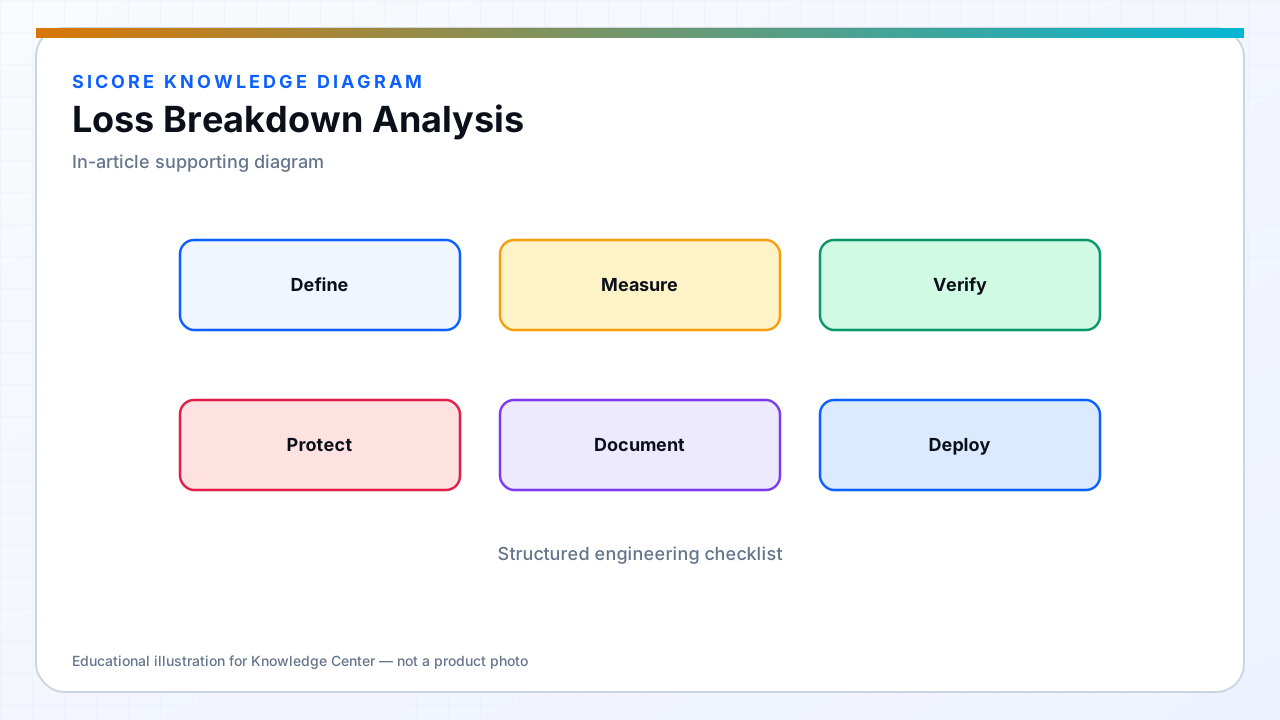
Measure at nominal and worst-case alignment. Use thermal camera to cross-check calculated device loss. Document assumptions for magnetics loss when direct measurement is impractical.
03Action
- Prioritize redesign where marginal improvement times fleet kWh is largest.
- Track breakdown revision to revision in product change records.