
Wiki article · Collection 04
Heatsink and Cooling
Engineering reference on Heatsink and Cooling for wireless power system design, integration, and deployment.
6 minArticle 47/50Power Electronics
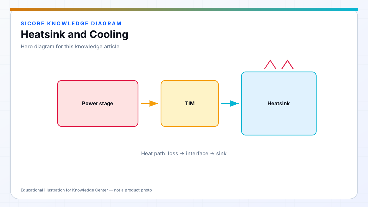
Heatsinks spread heat from device cases to air or enclosure surfaces. Floor pads may use aluminum spreaders into the pad plate; pedestal docks use finned heatsinks with fans. AMR receivers often rely on vehicle structure as heat sink with limited airflow.
Thermal interface material quality and mounting pressure repeatability dominate field performance.
01Design choices
- Natural convection for sealed pads — derate power or use heat spreading into concrete-safe materials.
- Forced air with filters for dusty warehouses — maintenance schedule mandatory.
- Heat pipes when remote fin stack improves service access.

02Integration
Model heat path from FET case to ambient including TIM and contact to pad cover. Fan failure must trigger derating or shutdown before junction limit — do not rely on operator hearing fan noise.
03Field notes
- Replace TIM on module swap — do not reuse dried paste.
- Blocked fan inlet from floor debris is common failure — design guards.