
Wiki article · Collection 04
Overvoltage Protection
Engineering reference on Overvoltage Protection for wireless power system design, integration, and deployment.
6 minArticle 43/50Power Electronics
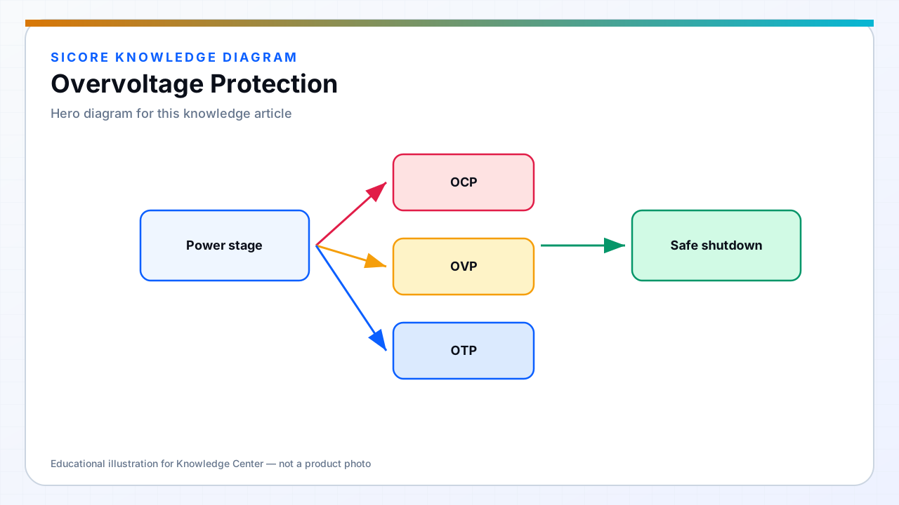
Overvoltage on the receiver occurs when coil open-circuits briefly, misalignment peaks voltage, or BMS opens contactor while current flows. On the dock, PFC or grid events can raise DC bus. Clamps, TVS, crowbars, and control shutdown each play roles.
OVP must be faster than device avalanche rating cumulative energy.
01Receiver strategies
- TVS or clamp on rectifier output sized for energy in leakage inductance.
- Active reduction of transmitter power via communication when voltage rises.
- SR and capacitor voltage ratings with margin for ring, not average.
02Dock strategies
Bus OVP lockout on PFC overvoltage or regen from connected vehicles if bi-directional paths exist. Crowbar last resort — know maintenance reset procedure.
03Testing
- Unload receiver during full charge current.
- Verify clamp survival count for repeated AGV disconnect events.