
Wiki article · Collection 04
Power Density
Engineering reference on Power Density for wireless power system design, integration, and deployment.
6 minArticle 14/50Power Electronics
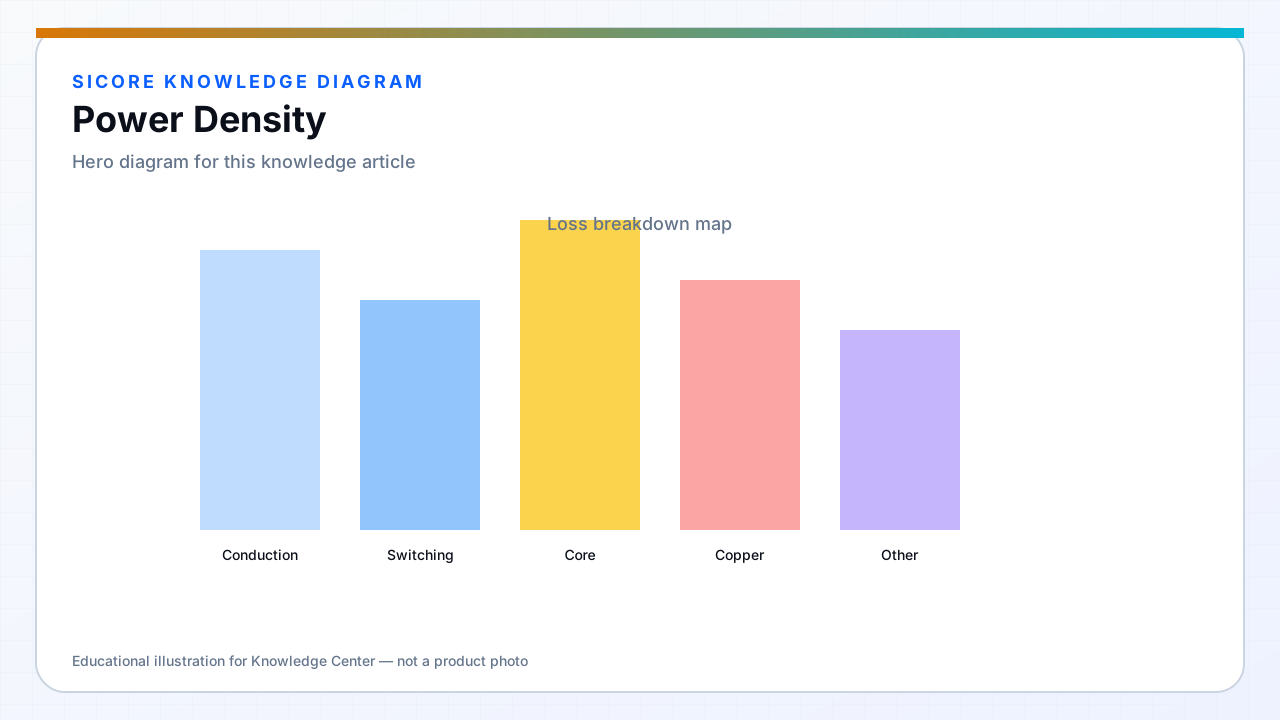
Power density is deliverable power per unit volume or area — critical when AGV belly clearance is tight and floor pads must survive forklift traffic. Higher density comes from better devices, higher frequency, improved magnetics, and integrated cooling — each with cost and complexity.
Marketing kW per square meter means little without stating gap, misalignment, coolant, and ambient.
01Levers
- Wide bandgap switches and optimized magnetics for smaller tanks.
- Higher frequency with Litz and careful AC loss control.
- Liquid or directed airflow in pedestals; heat spreading in floor assemblies.
- Multi-coil arrays with selective excitation for localized power delivery.

02Limits
EMI and safety clearances do not shrink with silicon scaling. Human-accessible surfaces have temperature and field exposure limits. Receiver volume on AMRs competes with battery and structure — density pushes against service access.
03Specification discipline
- Quote power density at worst-case alignment and ambient.
- Include inverter, coil, and rectifier loss in density figures, not coil alone.
- Document maintenance clearance for dense assemblies.