
Wiki article · Collection 04
EMI Reduction
Engineering reference on EMI Reduction for wireless power system design, integration, and deployment.
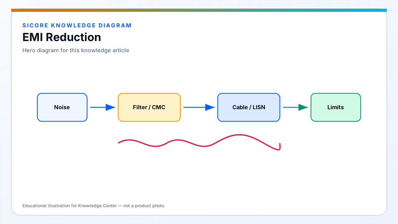
Wireless power is intentionally rich in magnetic fields — EMI engineering separates intentional coupling to the receiver from unintended noise on cables, structures, and nearby sensors. Dock inverters switch fast currents in loops that act as antennas unless filtered and laid out carefully.
EMI reduction starts at the switch node and DC bus, not only at the compliance test lab.
01Primary techniques
- Minimize switching loop area and use return paths under signals.
- Soft switching to reduce high-frequency content when topology allows.
- Input and output filters sized for both differential and common-mode paths.
- Shielding and ferrite on cables exiting the pad enclosure.
02WPT-specific issues
Coil leakage flux can induce noise in nearby wiring — route sensitive CAN and encoder cables away from pad edges. Harmonics of switching frequency interact with coil self-resonance; detuning from metal can shift emission peaks. Validate with the vehicle parked and absent — both configurations matter.
03Process
- Pre-compliance scans during prototype, not after mold tooling.
- Document filter and layout changes as controlled ECN for fleet consistency.
- Retest when cable lengths or site grounding differs from qualification setup.