
Wiki article · Collection 04
Power Electronics Checklist
Engineering reference on Power Electronics Checklist for wireless power system design, integration, and deployment.
6 minArticle 50/50Power Electronics
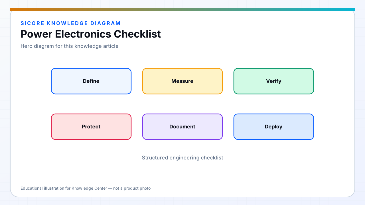
Use a structured checklist so dock and vehicle power stages do not ship with gaps in protection, EMC, or thermal margin. The list below summarizes classic gate items for AGV/AMR wireless power programs — adapt to your voltage class and regional codes.
01Design phase
- Topology and device selection documented with loss budget across alignment window.
- DC bus, pre-charge, discharge, and fuse coordination defined.
- Gate drive, dead time, and shoot-through protection verified on worst spread samples.
- Current and voltage sense placement validated for control and protection bandwidth.
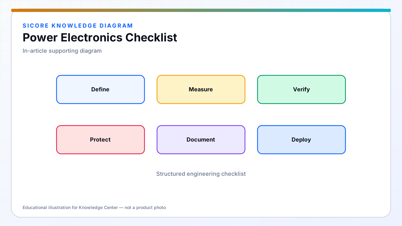
02Validation phase
- Efficiency map at min, nominal, max coupling and temperature corners.
- EMC pre-compliance and immunity per install class.
- Thermal soak at nameplate duty inside final enclosure.
- Fault matrix: OC, OV, OT, grid loss, comm loss, misalignment, foreign object if applicable.
03Production and field
Production test limits for key waveforms or power metrics. Service documentation for bus discharge, filter replacement, and firmware safe states. Fleet logging of faults tied to dock ID and alignment statistics for continuous improvement.
04Sign-off
- Cross-functional review: power, magnetics, firmware, safety, manufacturing.
- Change control for any post-qualification BOM or layout edit.
- Spares and obsolescence plan for semiconductors on multi-year AMR contracts.