
Wiki article · Collection 04
Voltage Sensing
Engineering reference on Voltage Sensing for wireless power system design, integration, and deployment.
6 minArticle 41/50Power Electronics
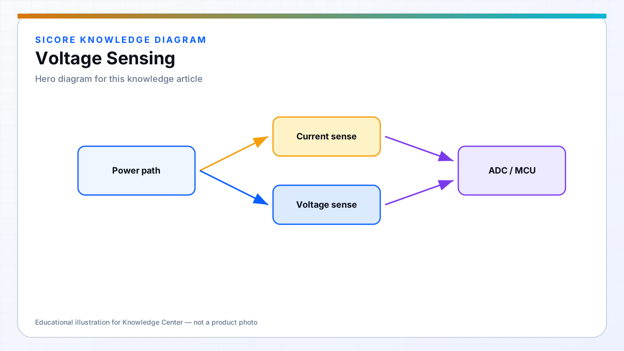
Voltage sensing provides feedback for PFC, inverter modulation, SR timing, and protection thresholds. High-frequency common-mode voltage on the switching node demands dividers and amplifiers rated for the environment or measurement on the isolated side.
Accuracy at light load matters for end-of-charge taper on AGV batteries.
01Techniques
- Resistive dividers with filtering for DC bus and battery.
- Isolated amplifiers or optocoupler sigma-delta for high common-mode environments.
- Peak detectors or ADC synchronized to switching for waveform analysis in development.
02Calibration
Account for divider tolerance and temperature coefficient in charge voltage accuracy specs. BMS on vehicle may disagree with receiver sense — define which measurement is authoritative for wireless power limit.
03Protection linkage
- Hardware comparators for fast OVP independent of firmware.
- Coordinated shutdown with transmitter when receiver reports overvoltage.
- Log OVP events with alignment metadata for root cause.