
Wiki article · Collection 02
Coupling Coefficient
Engineering reference on Coupling Coefficient for wireless power system design, integration, and deployment.
6 minArticle 02/16Resonant WPT
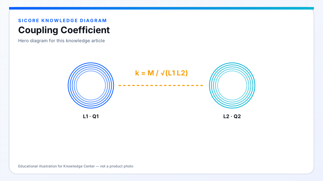
The coupling coefficient k quantifies how strongly two coils share magnetic flux. For self-inductances L1 and L2 and mutual inductance M, k = M / √(L1 L2). Perfect coupling is k = 1; practical wireless docks often operate well below that.
01What moves k
- Air gap: larger gap usually lowers k sharply.
- Lateral / angular misalignment: reduces overlapping flux.
- Coil size and geometry: DD, circular, and multi-coil arrays shape the k map.
- Ferrite and shielding: guide flux and can raise useful coupling while containing leakage.

02Design window, not a single number
A resonant charger is specified across a k range (best case, nominal dock, worst misalignment). Compensation and control must keep efficiency, voltage stress, and soft-switching margins acceptable across that window. Publishing only a peak k from a perfect lab alignment misleads fleet operators.