
Wiki article · Collection 02
Resonant Theory
Engineering reference on Resonant Theory for wireless power system design, integration, and deployment.
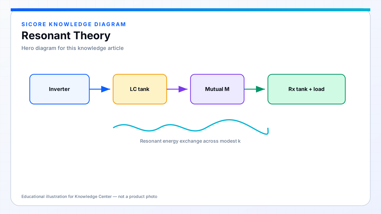
Resonant wireless power transfer tunes the transmitter and receiver so each forms a resonant tank near the operating frequency. When both sides ring together, reactive energy circulates locally in the tanks while real power crosses the air gap — even if the coupling coefficient is much lower than in a tightly seated inductive pad.
In circuit terms, inductance and capacitance exchange energy each half-cycle. At resonance, the imaginary part of the tank impedance approaches zero (topology-dependent), so a modest inverter voltage can drive meaningful coil current without fighting a huge reactive drop.
01Why resonance matters for docks
- Larger usable air gaps than tightly coupled IPT alone.
- More tolerance to lateral and angular misalignment in AGV/AMR docking.
- Higher coil currents at manageable semiconductor stress when tanks are tuned well.
- A clearer path to soft switching when the load trajectory is designed for ZVS/ZCS.
02What resonance does not remove
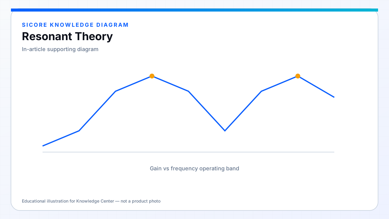
Resonance does not abolish physics. Copper loss, core loss, inverter switching loss, rectifier drop, and detuning from metal nearby still set efficiency and heat. Resonance is a tool for shaping impedance and gain — not a free efficiency upgrade.