
Wiki article · Collection 02
LCL Compensation
Engineering reference on LCL Compensation for wireless power system design, integration, and deployment.
6 minArticle 08/16Resonant WPT
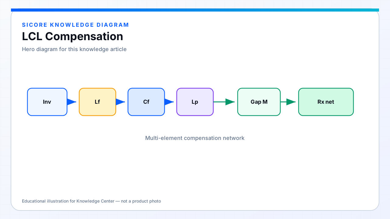
LCL compensation uses two inductors and a capacitor as a T-network filter between the inverter and the coil (or in related receiver forms). It can present a current-source character to the coil and attenuate high-frequency harmonics that would otherwise radiate or stress insulation.
01Engineering roles
- Shape coil current vs load for a target charging profile.
- Reduce harmonic content into the magnetic structure.
- Provide design knobs beyond a single series capacitor.
- Pair with secondary networks for double-sided compensation strategies.
02LCL vs LCC in practice
Naming varies across papers and vendors; always read the schematic, not only the acronym. Both families aim for controlled coil excitation and manageable gain. Selection depends on semiconductor voltage, available core volume, and whether the product roadmap already standardizes on one network for tooling and magnetics reuse.