
Wiki article · Collection 02
Series Resonance
Engineering reference on Series Resonance for wireless power system design, integration, and deployment.
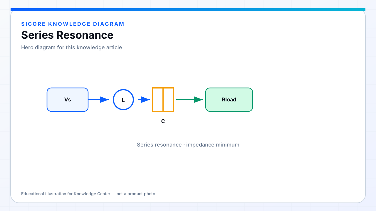
In a series-resonant tank, L and C are in series with the load path. At the resonant frequency the reactances cancel and the impedance magnitude reaches a minimum set mainly by resistance. Driven by a voltage-source inverter, series resonance tends to produce a current that rises as the load resistance falls — a behavior designers use carefully with battery loads.
01Characteristics
- Natural current peaking near resonance for a voltage-fed inverter.
- Simple capacitor count on each side when used as pure series compensation.
- Sensitive to shorted or very light loads depending on the full topology.
- Often combined into hybrid networks (for example series primary + parallel secondary).
02In wireless docks
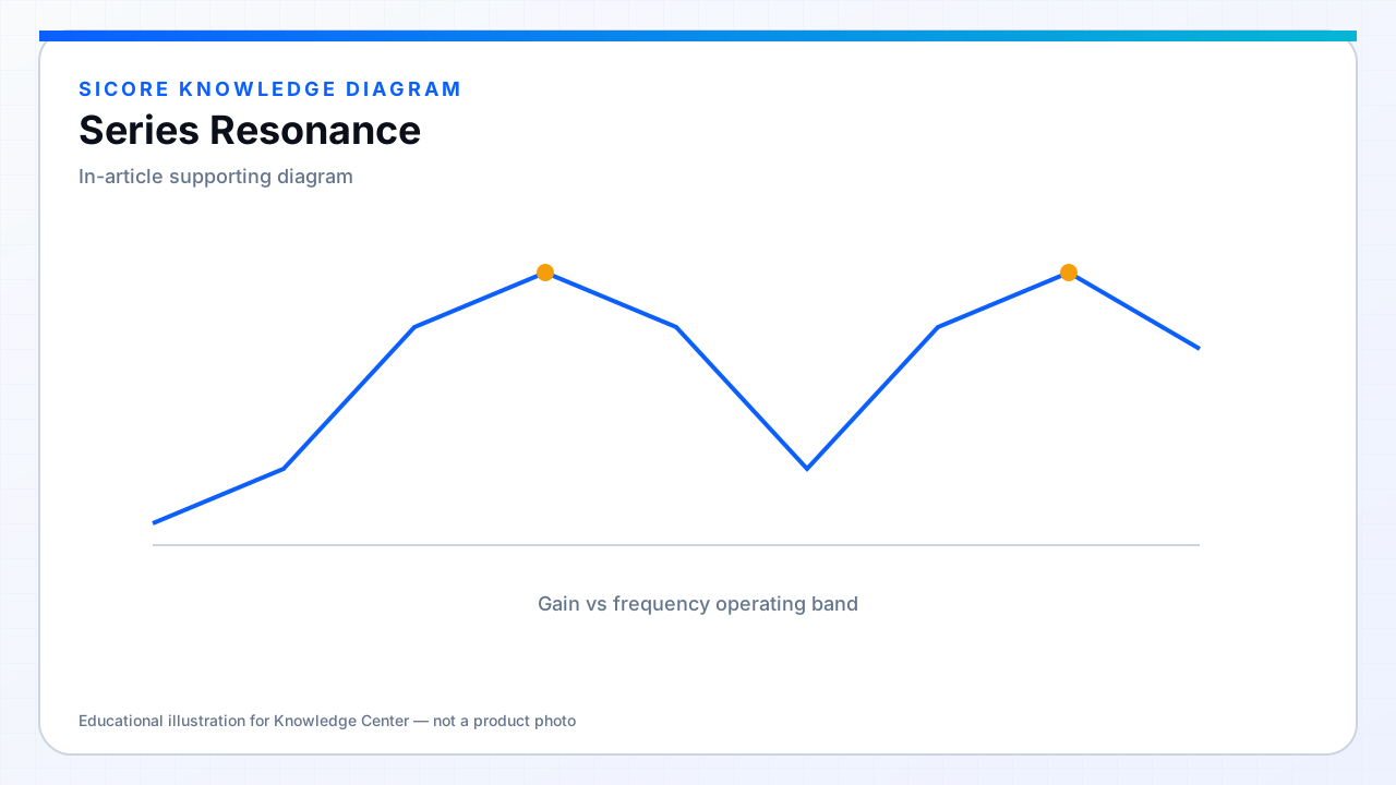
Pure series–series (SS) compensation is a classic teaching topology and still appears in products. It offers strong power capability when k is reasonable, but gain and bifurcation behavior must be mapped across misalignment. Many industrial designs move to LCC or other hybrids for a flatter gain and easier inverter current shaping.