
Wiki article · Collection 02
LCC Compensation
Engineering reference on LCC Compensation for wireless power system design, integration, and deployment.
6 minArticle 07/16Resonant WPT
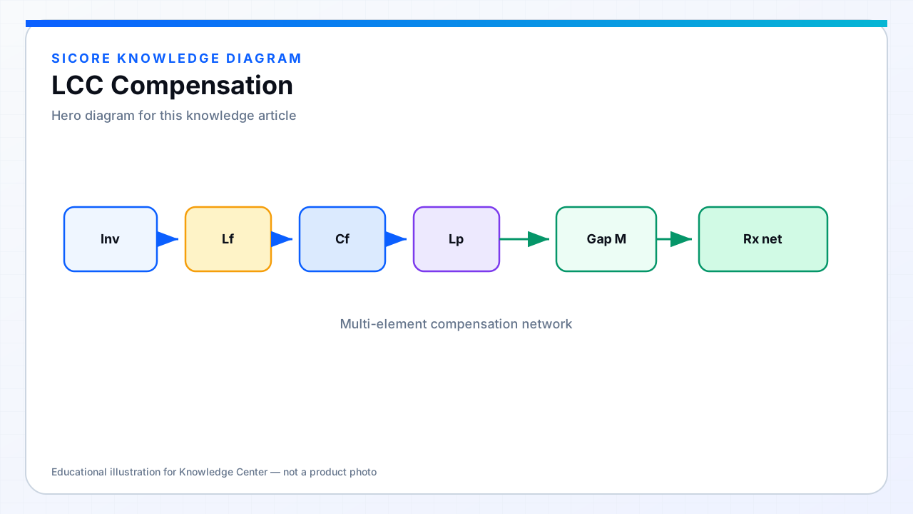
LCC compensation adds an inductor and two capacitors arranged so the primary (and often the secondary) presents a well-behaved resonant filter. A common primary LCC makes the coil current relatively insensitive to load in a designed band — closer to a current-source drive of the magnetic link.
01Why industry likes LCC
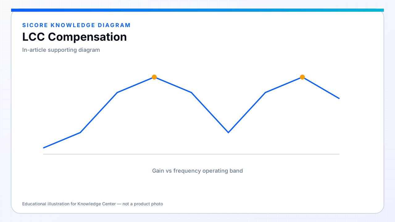
- Flatter power/gain curves across a practical k window.
- Easier inverter current shaping and ZVS planning than bare SS in some power classes.
- Secondary LCC can simplify rectifier voltage stress and battery charging profiles.
- Mature analysis literature for EV and industrial WPT.
02Cost of the extra parts
Extra magnetics and film capacitors add volume, loss, and BOM cost. Parameter drift and tolerance stack-up matter. LCC pays off when docking scatter is real and you need predictable pad current; it is overkill only if the mechanical alignment is already near-perfect and the power class is tiny.