
Wiki article · Collection 02
Parallel Resonance
Engineering reference on Parallel Resonance for wireless power system design, integration, and deployment.
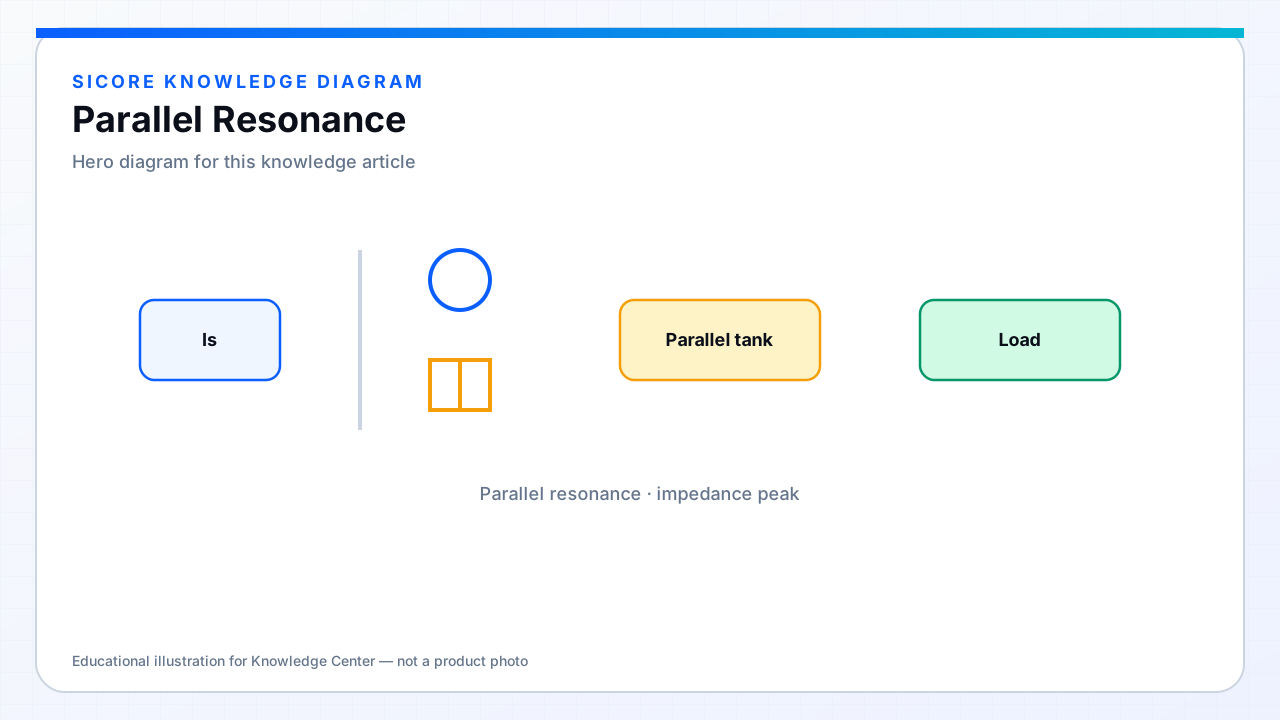
A parallel-resonant tank places L and C in parallel. Near resonance the impedance magnitude peaks. Voltage-fed and current-fed drive styles interact differently with parallel tanks than with series tanks, which is why compensation is usually discussed as a primary/secondary pair (SS, SP, PS, PP) rather than a single capacitor.
01When parallel shows up
- Secondary parallel compensation can behave like a voltage source for certain operating regions.
- Useful when the rectifier and battery want a more controlled voltage characteristic.
- Often appears inside LCC/LCL networks as part of a multi-element filter, not as a lone parallel coil capacitor.
02Design caution
Parallel resonance can produce high circulating currents and voltage magnification. Capacitor voltage ratings, coil insulation, and fault behavior (open receiver, foreign metal) need explicit analysis. Parallel is a tool inside a compensation strategy — not automatically “safer” or “more efficient” than series.