
Wiki article · Collection 04
Isolated Gate Drivers
Engineering reference on Isolated Gate Drivers for wireless power system design, integration, and deployment.
6 minArticle 32/50Power Electronics
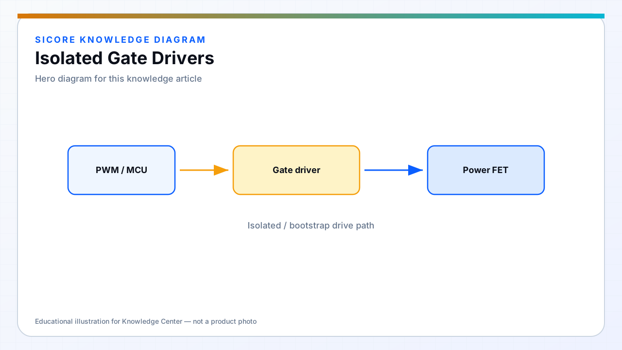
Isolated gate drivers transfer control signals across a barrier using transformers, capacitors, or optical links while providing appropriate gate drive power on the floating side. Full-bridge WPT inverters with true floating high-side references and multi-kV safety partitions rely on them.
Propagation delay and CMTI (common-mode transient immunity) must exceed switching node slew in harsh layouts.
01Selection
- CMTI rating above measured dV/dt on the switching node.
- Secondary-side UVLO and fault feedback to primary controller.
- Isolated bias supply or integrated power for secondary side.
02Layout
Keep clearance between primary and secondary per isolation rating. Return path for gate current stays on the secondary side — do not route gate return across the isolation barrier on a single-layer board.
03Dock applications
- Safety-isolated control from operator-accessible service ports to power stage.
- Floating SR drive on receiver when topology requires it.
- Redundant drive channels in high-availability charging lanes.