
Wiki article · Collection 02
Double-Sided Compensation
Engineering reference on Double-Sided Compensation for wireless power system design, integration, and deployment.
6 minArticle 10/16Resonant WPT
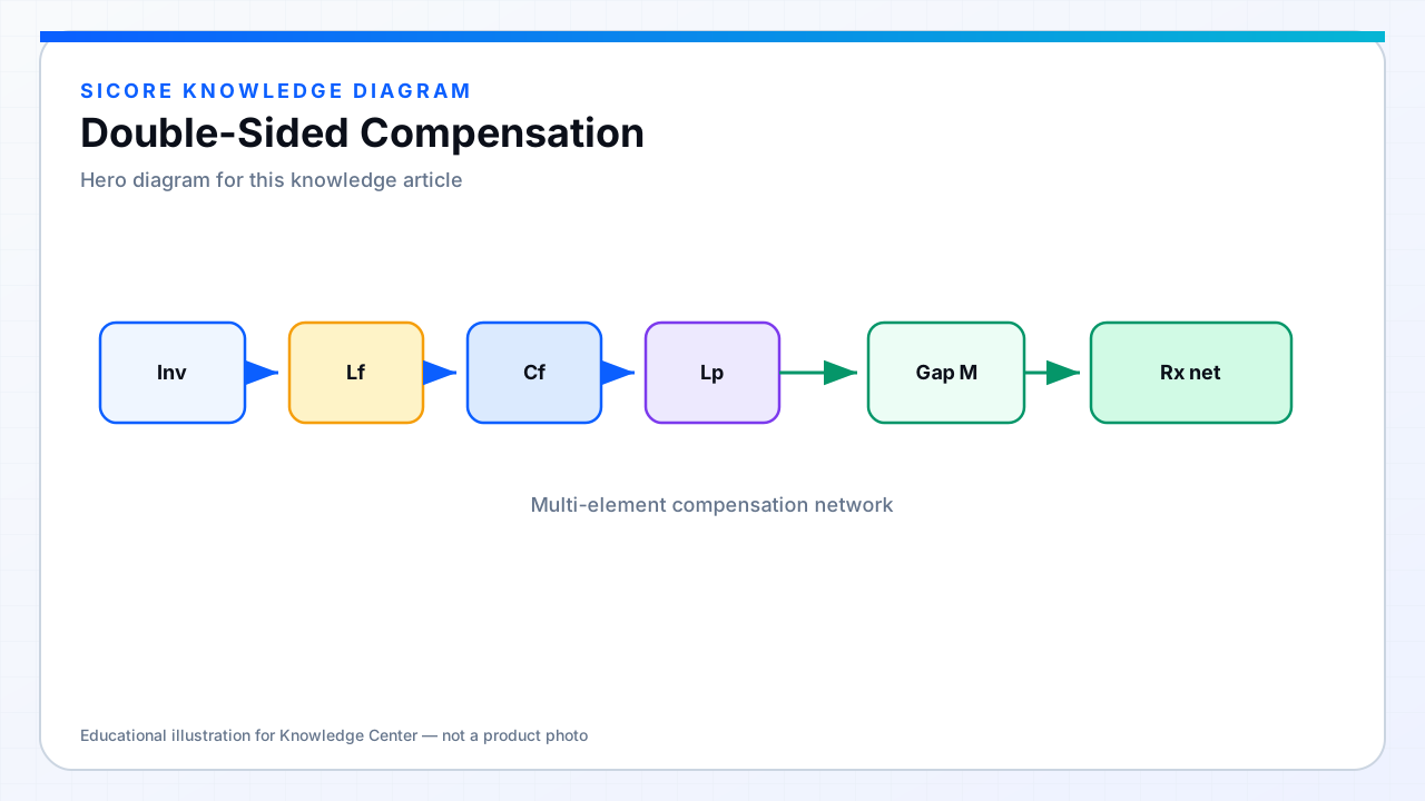
Double-sided compensation places resonant networks on both the transmitter and the receiver. Each side cancels most of its own coil reactance so real power transfer is not choked by huge reactive drops, and the inverter and rectifier see more intentional impedances.
01What you gain
- Higher transferable power for a given semiconductor VA rating.
- Better efficiency across a designed k band when both tanks track resonance.
- More degrees of freedom to shape load-independent current or voltage regions.
- Clearer partition of primary control vs secondary regulation roles.
02Integration note
Receiver compensation lives on the vehicle or robot — space, heat, and ingress protection constrain capacitor technology and inductor cores. Primary compensation lives in the pad or wall box with different cooling. Double-sided design is therefore a mechanical packaging problem as much as a Bode-plot problem.