
Wiki article · Collection 01
Coupling Mechanisms
Engineering reference on Coupling Mechanisms for wireless power system design, integration, and deployment.
6 minArticle 15/16Fundamentals
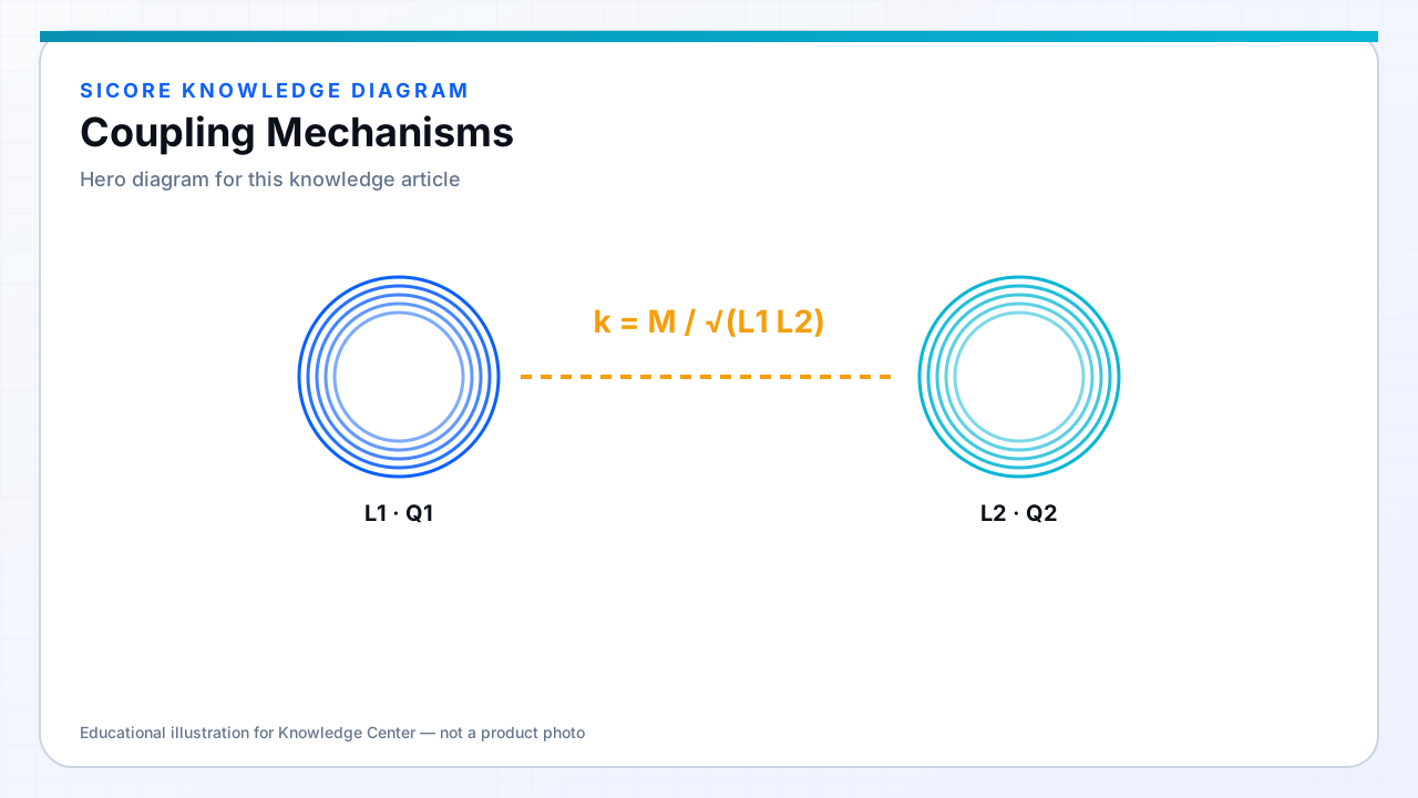
“Coupling mechanism” names the physical channel that carries energy across the gap. Product decisions start here: magnetic for most docks, electric for some plate interfaces, radiative for distance-oriented links.
01Mechanisms at a glance
- Magnetic inductive: strong short-gap coupling, transformer-like.
- Magnetic resonant: tuned tanks for looser coupling and larger gaps.
- Capacitive: electric-field plates, dielectric-sensitive.
- Radiative RF/microwave/optical: propagating waves, distance-first.
02Selection checklist
List gap, alignment tolerance, power level, enclosure materials, EMI limits, and human exposure rules. Then pick the mechanism that meets power and safety with the simplest infrastructure. For sealed industrial opportunity charging, magnetic inductive or resonant coupling is the usual winner; other mechanisms fill specialized niches.