
Wiki article · Collection 01
Near-Field vs Far-Field
Engineering reference on Near-Field vs Far-Field for wireless power system design, integration, and deployment.
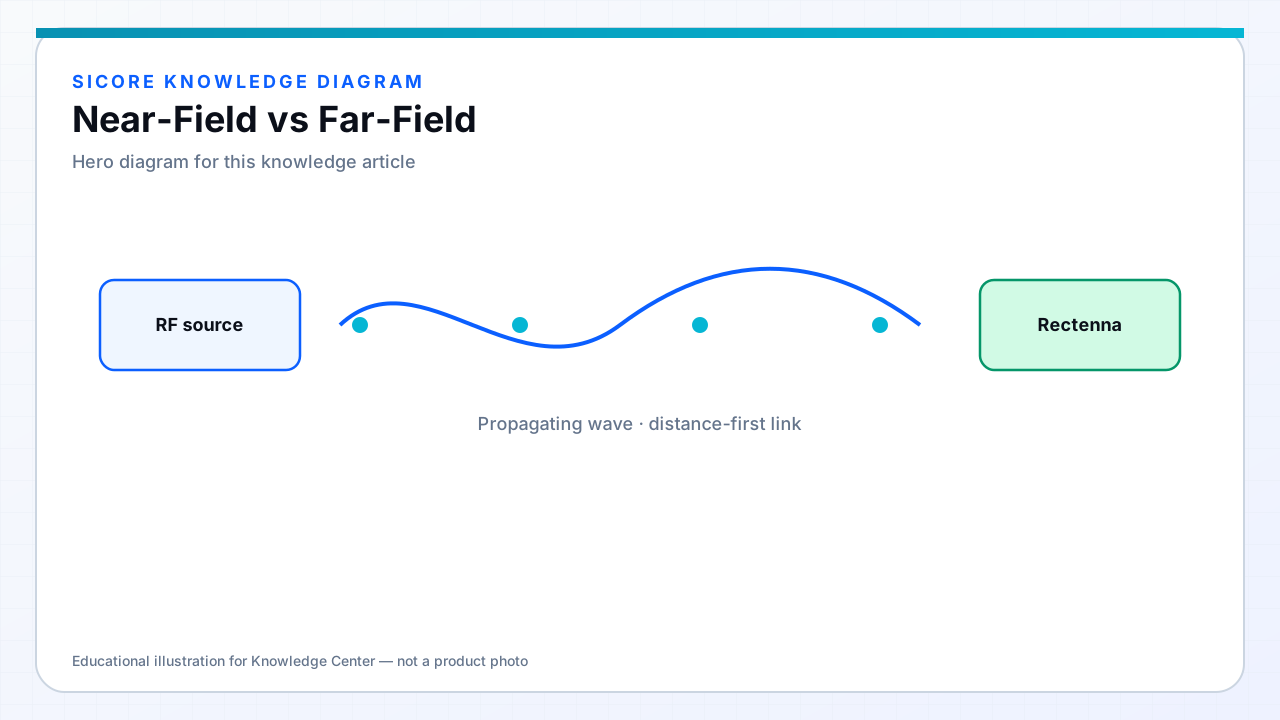
Near-field wireless power operates in the reactive zone close to the transmitter — inductive, resonant magnetic, or capacitive interfaces. Far-field systems radiate propagating waves. The boundary is physical, not marketing: it changes efficiency curves, safety analysis, and product architecture.
01Quick comparison
- Near-field: short gap, high potential efficiency, pad/dock form factors, strong industrial traction.
- Far-field: longer distance, lower power density at the receiver, beam/antenna design dominates.
- Near-field EMI is mostly magnetic/electric local fields; far-field adds radiated RF compliance complexity.
- Docking robots → near-field. Remote ultra-low-power sensors → often far-field RF.

02Choosing for a project
If the vehicle can present a coil to a pad within a controlled gap and alignment window, near-field magnetic WPT is usually the engineering default. If the device cannot dock and only needs microwatts to milliwatts, far-field RF harvesting may win. Mixing the two in one product is uncommon; mixing them in one facility is normal.