
Wiki article · Collection 02
Resonant Stability
Engineering reference on Resonant Stability for wireless power system design, integration, and deployment.
6 minArticle 16/16Resonant WPT
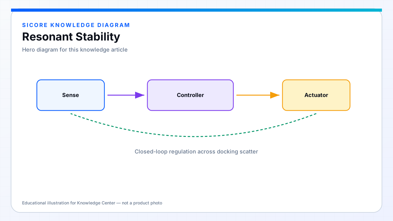
Resonant stability means the charger stays in a safe, predictable operating region as conditions change — no uncontrolled bifurcation jumps, no loss of ZVS cascades, no thermal runaway in tanks, and no control loops that fight each other.
01Disturbances to budget
- Mechanical: gap and alignment scatter every dock cycle.
- Electrical: battery SOC, sudden load steps, rectifier mode changes.
- Thermal: L and C drift as coils and capacitors heat.
- Environmental: steel floors, nearby carts, foreign metal (FOD events).
- Software: frequency sweep rate, communication latency, dual-loop conflict.
02Stability engineering
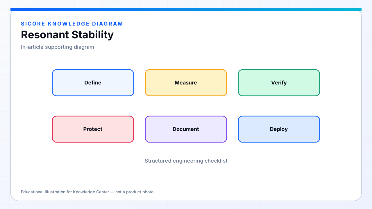
Map the gain and ZVS regions across k and load. Limit actuator authority so the controller cannot park on unstable branches. Validate with worst-case metal and temperature, not only nominal pads. Resonant WPT products earn trust when stability is demonstrated in the dock map the robot will actually see.