
Wiki article · Collection 02
Power Regulation
Engineering reference on Power Regulation for wireless power system design, integration, and deployment.
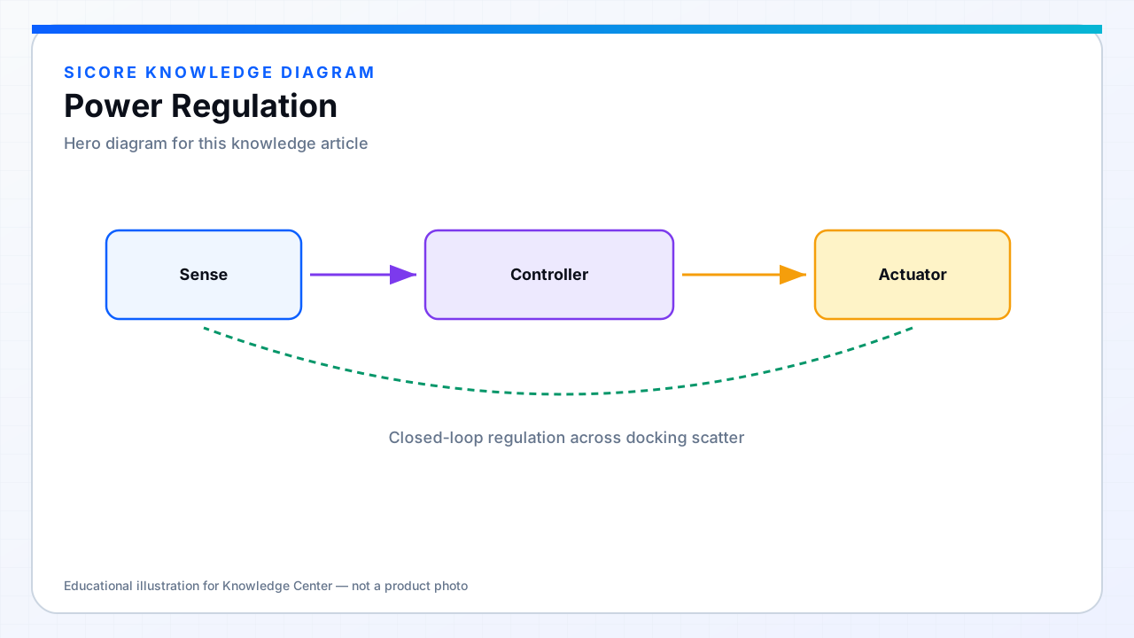
Batteries need controlled current and voltage, not a fixed resonant party. Regulation layers sit on top of the tuned tanks: the primary may modulate frequency, phase shift, or DC rail; the secondary may use a DC/DC stage for precise CC/CV; both sides exchange signaling for setpoints and faults.
01Common actuators
- Frequency modulation around the gain curve.
- Phase-shift or duty control of a full-bridge inverter.
- Primary DC bus adjustment (controlled front-end).
- Receiver buck/boost charger for fine battery profiles.
- Detuning or matching network actuators in advanced systems.
02Industrial requirements
Fleet chargers must regulate under misalignment, hot ferrite, aging capacitors, and pack impedance that changes with SOC and temperature. Loop bandwidth should reject docking disturbances without hunting into frequency-splitting regions. Telemetry of gap quality, efficiency, and thermal headroom turns regulation into operations data — not only a lab waveform.