
Wiki article · Collection 01
Power Transfer Principles
Engineering reference on Power Transfer Principles for wireless power system design, integration, and deployment.
6 minArticle 13/16Fundamentals
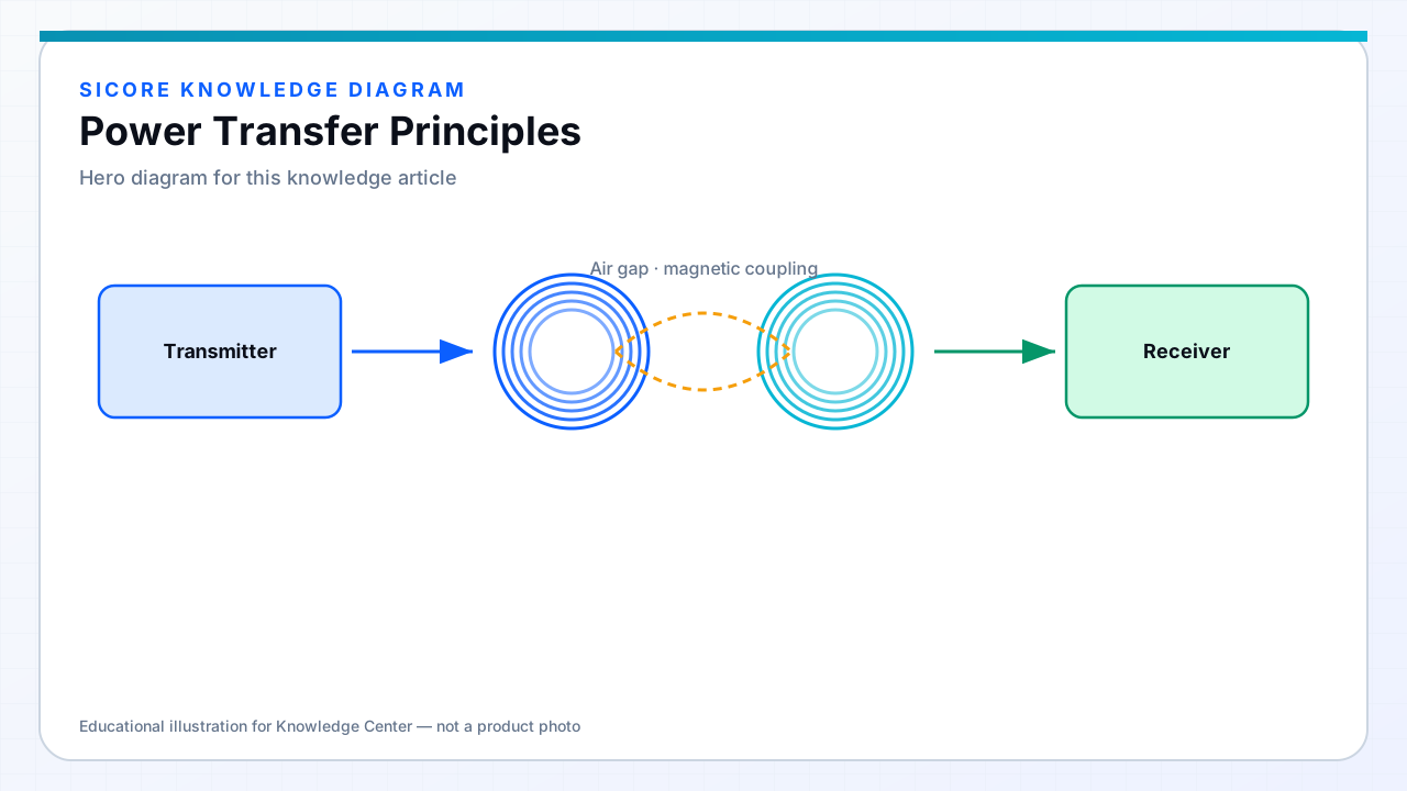
Wireless power is still ordinary electromagnetics and power electronics. Delivered power depends on source capability, coupling, resonance (if used), load impedance, and losses in copper, core, switching devices, and rectifiers.
01Magnetic near-field essentials
- Ampère / Faraday: time-varying current → time-varying flux → induced voltage in the receiver.
- Mutual inductance M links the coils; coupling k = M / √(L1 L2).
- At a given voltage/current stress, higher k generally means easier high-efficiency transfer.
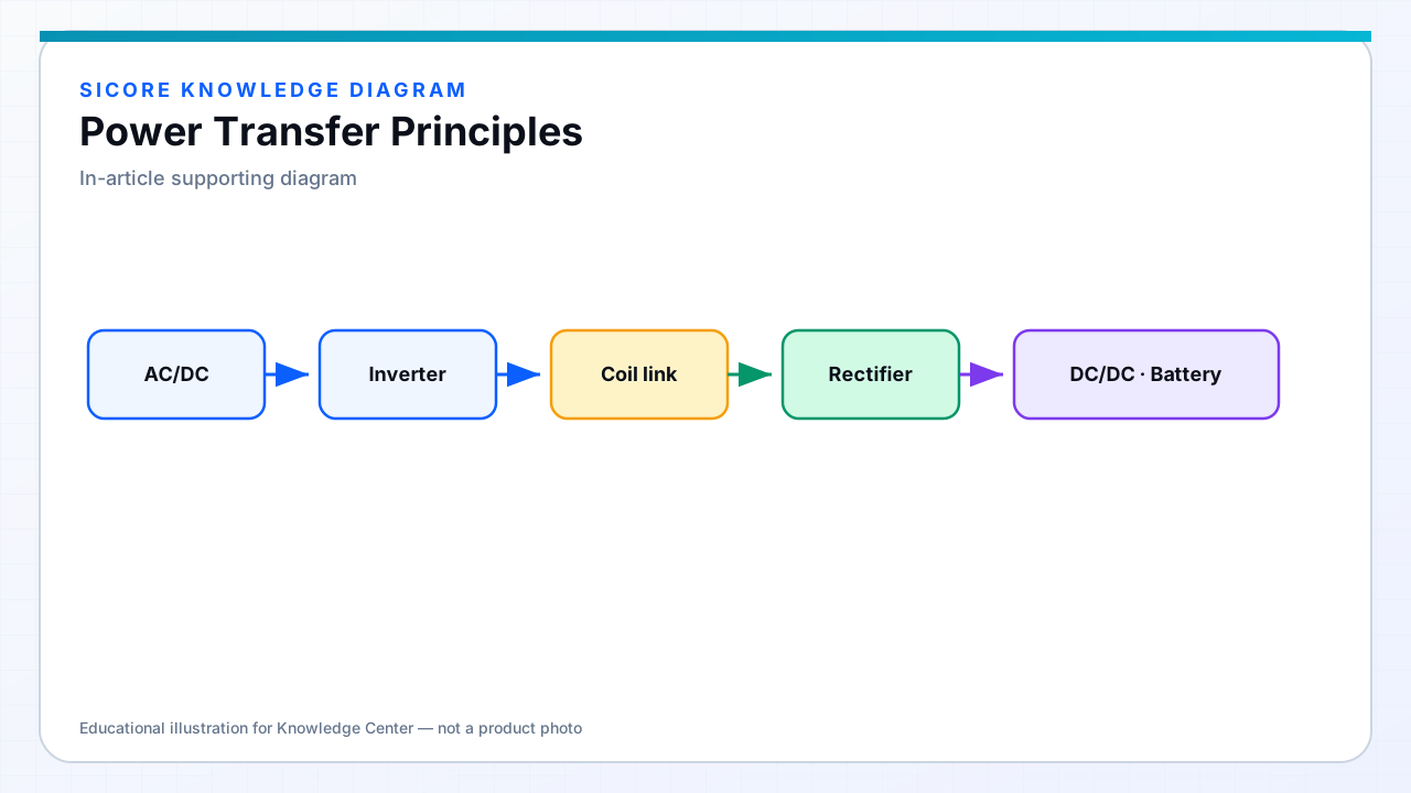
- Compensation networks cancel reactive energy so the inverter sees a manageable load.
02Control view
Real chargers regulate something measurable: receiver voltage, battery current, or transmitter rail. As the battery SOC rises or alignment drifts, the reflected impedance changes. Controllers adjust frequency, phase, duty, or matching networks to hold the operating point inside efficiency and thermal limits.